Transformer Tank Types: Depending upon the position of the joint between the upper and lower parts, we
have two types of construction: the conventional tank and the bell tank.
Join EEE Made Easy Whatsapp Channel
Classification of Transformer Tanks
Conventional tank
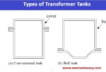
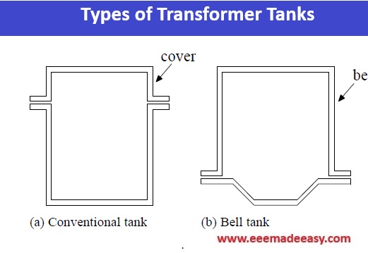
This type of construction has a top cover as shown in Figure (a). Since the joint is usually above the top yoke level, it facilitates proper placement of magnetic shunts on the tank wall for an effective stray-loss control.
The disadvantage is that the core and the windings are not visible on site when the cover is removed. Hence, for inspection of the core-winding assembly, a crane with higher capacity is required to remove the assembly from the tank.
Books for All Competitive Exams
Bell tank
In this construction, shown in Figure (b), the joint between the two parts is at the bottom yoke level to facilitate the inspection of the corewinding assembly on site after the bell is removed.
Thus, it consists of a shallow bottom part and a bell-shaped top cover. The bell construction may not be
convenient for proper placement of magnetic shunts if the joint is at such a height from the bottom that it comes in the path of the leakage field. This may lead to a bolt overheating problem.
For the above two types of tank, either a plain or a shaped tank can be used.
Plain tank
This kind of tank has rectangular shape and is simple in construction. It facilitates standardization, and the design of stiffeners is also straightforward. It usually leads to higher oil and steel quantity in high voltage
transformers.
If special detachable (bolted) bushing pockets are used for a center line lead HV winding arrangement, some saving in oil quantity can be achieved.
This is usually done in large high voltage transformers.
Shaped tank
In order to save oil quantity, the tank is shaped so that its volume reduces. The tank shaping is mainly influenced by electrical clearances (between high voltage leads and the grounded tank), transport considerations, tap changer mounting arrangements, etc.
The lower portion of the tank may be truncated in order to facilitate the loading of a large transformer on some specific type of wagon (in the case of rail transport) and/or to reduce oil quantity. The tank walls
may be curved/stepped to reduce the tank size and volume.
A shaped tank has the advantage that the curved portions of its walls give a stiffening effect.
However, its design is more complex, requiring greater engineering and manufacturing efforts. Also, placement of magnetic shunts or eddy current shields on it may be cumbersome.
The joint between the two parts of the tank can be either bolted or welded type, which gives the following two types of construction.
Bolted construction
This construction, although preferred for easy serviceability, has a major disadvantage in that leaks can develop if gaskets deteriorate over a period of time.
Oil leakage problems can occur if there is unevenness in the plates that are bolted or if the gaskets are overcompressed.
The bolted joint may also lead to overheating hazards in large transformers.
Welded construction
This type of construction eliminates probable leakage points since the two parts of the tank are welded together.
It can thus ensure leak-proof joints throughout the service life of the transformer.
But if a problem or fault develops inside the transformer, a dewelding operation has to be done
and there is a limit on the number of times one can do the de-welding and subsequent welding operations.
C-shaped clamps are used during the welding operation and a thin gasket is provided between the two curbs so that the welding spatters do not enter inside the tank.
Some arrangement is provided inside the tank at the top for arresting the buckling of the cover under lifting
loads.
Depending on whether the tank is totally sealed from the outside atmosphere or is in contact with the atmosphere, the following two types of construction exist.
Breathing tank construction
Ambient temperature and load variations result in change of oil volume. The conservator fitted on the tank top allows these volume changes.
It is partially filled with oil and it communicates with the atmosphere through a breather containing a moisture-absorbing material.
In order to eliminate the contact of oil with the atmosphere, a constant oil pressure system is used in which a flexible bag (membrane) fitted inside the conservator communicates with the outside air.
The air bag contracts or expands depending on changes in the oil volume.
This construction is commonly used for large power transformers.
Sealed tank construction
In this type of arrangement, free space (filled usually with nitrogen gas) is provided in the tank for oil expansion based on the maximum expected oil temperature.
The contact of oil with the outside atmosphere is totally eliminated.
The tank is designed to withstand the pressure variations due to changes in the oil volume.
The construction has a disadvantage in that with a sudden fall in temperature, gases may be released from the oil, seriously affecting the dielectric strength of the insulation system.
Higher clearances have to be provided between electrodes separated by the combined oil and gas spaces (as compared to conventional clearances for oil immersed electrodes).
There are some special types of tank construction based on their application and features, as given below.
Corrugated tank
This construction is used in small distribution transformers to obviate the need of providing radiators separately.
Corrugations are made by folding a steel sheet continuously on a special purpose machine.
These corrugations are then welded on a steel frame to form a tank wall. The corrugations provide an adequate cooling surface and also play the roll of stiffeners.
In distribution transformers, the use of the corrugated tanks can reduce the manufacturing (fabrication) time substantially.
Cover-mounted construction
In this type of construction, the core and the windings are attached to the tank cover. Lifting lugs/bollards are provided on the frames.
The construction facilitates connections from the windings to cover mounted accessories like an in-tank type OLTC and small bushings.
Access to the lifting lugs/bollards is provided through inspection openings on the cover.
The complete core-winding assembly with the top cover can be lifted by means of the lifting lugs/bollards and lowered into the tank.
The whole arrangement can be made compact and simpler.
For the servicing purpose, the untanking of the core-winding assembly is possible without removing the bushing connections.
Perforated tank
This type of tank is used in dry-type transformers, wherein it is used just as an enclosure to house the active parts.
The perforations allow the flow of air for cooling the inside active parts.
The construction generally consists of detachable panels which cannot take any lifting load.
The absence of oil and the presence of perforations usually lead to higher noise levels in dry transformers as compared to oil-cooled transformers, and special measures need to be taken to reduce them.
Read More on Transformer
- Transformers MCQ questions set 1
- Transformers MCQ Questions- Set 2
- Transformer MCQ Questions Set 3
- Efficiency of Transformer|Equation & Example
- Losses in a Transformer
- [Solved]Transformer Voltage Regulation Problem
- LVDT|Linear Variable Differential Transformer
- Autotransformer|Application of Autotransformer
- Transformers Electrical Engineering Interview Questions
- Why Transformers Hum: 7 Shocking Causes and Expert Solutions You Need to Know
- Single-phase transformer Connections Series & parallel
- Hysterisis and Eddy current losses
- Special Transformers
- Static Electrification in transformers
- Magnetostriction and its ill effects
Join EEE Made Easy Whatsapp Channel
Download EEE Made Easy Ebook PDF Free
Latest Posts in EEE Made Easy
- Transformer Tank Types|Classification of Transformer Tanks
 Transformer Tank Types: Depending upon the position of the joint between the upper and lower parts, wehave two types of … Read more
 - Static Electrification in transformersStatic Electrification in transformers: Generation of static charges, caused by oil streaming on a solid insulating component, is responsible for … Read more
- Special TransformersSpecial Transformers: There are some special transformers like Rectifier Transformers,Converter Transformers for HVDC,Furnace Transformers and Phase Shifting Transformer. Special Transformers … Read more
- Magnetostriction and its ill effectsMagnetostriction and Its ill-effects:The property of ferromagnetic materials, due to which their dimensions are changed due to change of magnetic … Read more
- Losses in a TransformerLosses in a Transformer:The losses which occur in an actual transformer are: (i) Core or iron losses (ii) Copper losses … Read more
- Electrician Printing Dept Syllabus Kerala PSC|771/2025 Syllabus Kerala PSCElectrician Printing Dept Syllabus Kerala PSC : KERALA PUBLIC SERVICE COMMISSION DETAILED SYLLBUS FOR THE POST OF ELECTRICIAN GR.II IN … Read more
- Energy Efficient Lamps|CFL, LED lampsEnergy Efficient Lamps: CFL (Compact Fluorescent lamp ) and LED (light emitting diodes) lamp are Energy Efficient Lamps. Energy Efficient … Read more