Special Transformers: There are some special transformers like Rectifier Transformers,Converter Transformers for HVDC,Furnace Transformers and Phase Shifting Transformer.
Special Transformers
1 Rectifier Transformers
2 Converter Transformers for HVDC
3 Furnace Transformers
4 Phase Shifting Transformer
For More reference, Check this Book on Transformer. book Link 2
Rectifier Transformers
Duties of rectifier transformers serving special industrial loads are more stringent than conventional transformers.
Electrical energy in the form of direct current is required in electrolytic processes used in aluminum smelters and chemical plants (producing chlorine, soda, etc.).
Various methods used for converting AC into DC in earlier days included use of motor-generator sets,
rotary converters, and mercury arc rectifiers.
Due to rapid developments in power electronic converters and switching devices, transformers with modern
static converters (rectifiers) are being widely used for current ratings as high as hundreds of kilo-amperes.
Design and manufacture of transformers for the rectifier duty poses certain challenges.
Complex winding arrangements, high currents and associated stray field effects, additional losses and heating effects due to harmonics, the necessity of maintaining constant direct current, etc. are some of the special characteristics of the rectifier transformers.
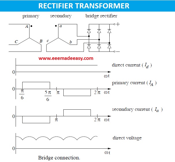
Bridge connection
One of the most popular rectifier circuits, three-phase six-pulse bridge, is shown
in Figure 11.1. It gives a 6-pulse rectifier operation with the r.m.s. value of the
secondary current for an ideal commutation condition (zero overlap angle) as

where Id is the direct current. For a transformer with unity turns ratio, the r.m.s. value of the primary current is also given by the above expression.
The average value of the direct voltage is
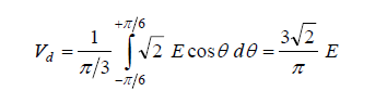
where E is the line-to-line r.m.s. voltage.
The secondary winding does not carry any direct current (the average
value over one cycle is zero). The ratings of both primary and secondary
windings are equal, which can be obtained by using Equations

Thus, in the bridge connection the capacity of the transformer is well utilized because the required rating of (1.047 Pd ) is the minimum value for the 6-pulse operation.
The bridge connection is simple and widely used.
Features of rectifier transformers
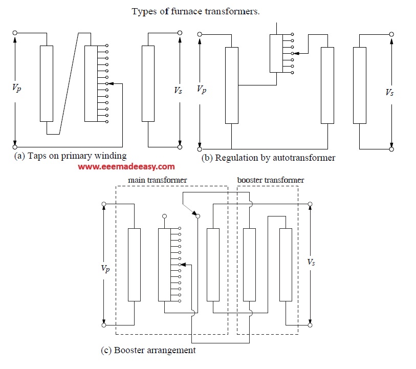
Rectifier transformers are used in applications where the secondary voltage is required to be varied over a wide range at a constant current value. It is extremely difficult and uneconomical to have taps on the secondary winding because of its very low number of turns and a high current value.
The taps are either provided on the primary winding, or a separate regulating transformer (autotransformer) is used feeding the primary of the main transformer, which can be accommodated in the same tank. Various circuit arrangements that can be used to regulate the secondary voltage are elaborated in.
For higher pulse operations, extended delta connections are shown to be more advantageous than zigzag connections, as they result in lower eddy losses and short-circuit forces.
The output connections, which carry very high currents, increase the impedance of the transformer significantly.
The increase in the impedance value due to these connections can be calculated for a single conductor according to above Equation .
For go-and-return conductors of rectangular dimensions, the impedance can be calculated using the formulae given in For large rating rectifier transformers, the field due to high currents causes
excessive stray losses in the structural parts made from magnetic steel.
Hence, these parts are usually made from nonmagnetic steel.
Rectifier transformers are subjected to harmonics due to non-sinusoidal current duties. Hence, sometimes the pulse number is decided by harmonic considerations. Due to harmonics, more elaborate loss calculations are required for the rectifier transformers compared to the conventional transformers
Sometimes the core of the rectifier transformer supplying power electronic loads is designed to have a small gap in the middle of each limb to limit the residual flux and to keep the magnetizing reactance reasonably constant.
This feature also limits the inrush current thereby protecting the power electronic devices. Under normal operating conditions, the core flux fringing out in the gap between the two core parts hits the inner winding causing high eddy losses.
In order to mitigate this effect, the windings may also have to be designed with a gap at the location facing the core gap.
Because of possibilities of rectifier faults, special design and manufacturing precautions are taken for rectifier transformers. It is generally preferred to design the rectifier transformers with larger core area with
corresponding smaller number of turns to reduce short-circuit forces .
Disktype windings are preferred since they have better short-circuit strength compared to layer windings. Quality of drying/impregnation processes and integrity of clamping/support structures have to be very good.
The paper insulation on winding conductors can also be strengthened.
Converter Transformers for HVDC
There has been a steady increase in high voltage direct current (HVDC) transmission schemes in the world because they offer many advantages compared to HVAC systems.
The converter transformer is one of the most important and costly components of the HVDC transmission system.
The converter transformer design has much in common with that of the conventional power transformer except for a few special design aspects.
Configurations
A standard 12-pulse converter configuration can be obtained using star-star and star-delta connections with one of the following arrangements: 6 single-phase two-winding, 3 single-phase three-winding and 2 three-phase two-winding constructions.
The arrangements are shown in Figure below.
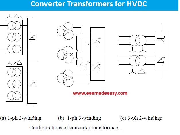
The weight and size of an individual transformer are highest and the overall cost (with all transformers considered) is lowest in the three-phase two-winding configuration, whereas the weight and size of an individual transformer are lowest and the overall cost is highest in the single-phase two-winding
configuration.
Since the cost of a spare transformer in the single-phase two winding configuration is lowest (that of only one of the six transformers), it is more commonly used.
On-load tap changer (OLTC):
The OLTC of a converter transformer plays a crucial role in HVDC transmission systems. Its tap position is adjusted to obtain a voltage condition that minimizes the reactive power requirement of HVDC
converters (i.e., the firing angle of converters is kept as minimum as possible).
Hence, the OLTC is an important constituent of the HVDC control scheme. The number of OLTC operations in a converter transformer is usually much higher than that in a conventional power transformer for the same reason.
The OLTC is used for effective control of the DC voltage and the power flowing through the
HVDC line.
Leakage impedance:
The leakage impedance of the converter transformer is the principal component of the commutating reactance, which limits the rate of rise of the loop current during the small overlap period when current is transferred from one valve to another.
Thus, the leakage impedance helps in preventing instantaneous current transfer which otherwise would result in high di dt values damaging the valves.
The leakage impedance value has to be judiciously selected; a higher value reduces the rate of rise of the loop current during the current commutation process, but increases the overlap angle and the reactive
power demand of the converters.
The permissible tolerance on the impedance value of the converter transformers is usually lower than that on the impedance of the conventional transformers to reduce distortions in DC voltage waveforms
and noncharacteristic harmonics.
DC bushings:
Creepage requirements of DC bushings are higher.
The DC creepage withstand of an insulator can be about 30% lower than the AC withstand. While for conventional transformers, a creepage distance of about 31 mm/kV is specified for very heavily polluted areas, the creepage distance of as high as 40 mm/kV may be specified for DC bushings in the converter
transformers.
Harmonics:
One of the most severe duties of the converter transformers is the presence of harmonics. Due to harmonics, eddy losses in windings and stray losses in structural components are higher in the converter transformers than in the conventional transformers.
For a 6-pulse operating condition, the harmonics generated are 6k 1, where k is an integer. For a 12-pulse operating condition, the harmonics generated are 12k 1.
Thus, the higher the pulse number the higher is the frequency of the lowest order harmonic produced. But as the pulse number increases, the number of transformers required is more and also the
complexity of transformer connections increases.
For a 24-pulse operating condition, use of zigzag windings or an extended delta connection is required.
Furnace Transformers
A transformer supplying an arc furnace has to deliver unusually high currents over a wide range of voltage. Power ratings between 50 and 100 MVA are quite common now with the secondary currents of more than 50 kA.
Furnace transformers have special features for handling very high currents compared to
conventional transformers.
Since the LV winding current is high, its voltage is better controlled by providing taps on the HV winding.
An arc furnace has three electrodes connected to the secondary terminals of the furnace transformer which has to be specially designed to withstand frequent short circuits on the secondary side. Currents drawn in the arc furnace are characterized by wide fluctuations and unbalanced conditions, which lead to problems of voltage drops, harmonics, etc.
These effects can be mitigated by supplying furnaces directly from a high voltage transmission line having high capacity (i.e., an adequate short-circuit level at the supply point) through a furnace transformer.
In such a case, when the voltage ratio is high, suitable measures should be taken for protecting the
secondary winding against the electrostatically transferred voltages from the high voltage primary winding.
These measures are connection of a surge arrester, or a capacitor, between the secondary terminals and a ground and placement of an electrostatic shield between the primary and secondary windings.
The leakage reactance of the furnace transformer affects the furnace operation since it is added to the reactance of the high current connections between the transformer secondary terminals and electrode tips.
The higher the reactance, the lower the useful service currents are, thereby reducing the
efficiency of the operation.
Hence, the leakage reactance needs to be kept as small as practically possible with due consideration to the short-circuit withstand of windings and clamping/support structures.
Also, a certain minimum value of reactance is required in the furnace circuit to stabilize arcs. In large furnace
installations, the low voltage connections usually provide the necessary reactance. For smaller installations, a reactor may have to be added in series with the primary winding to give a sufficient reactance value for the stability.
The series reactor, which may be housed in the tank of the furnace transformer, is usually provided with taps so that the reactance value can be varied for an optimum performance. Hence, depending on the rating of furnace installation and its inherent reactance, the leakage reactance of the furnace transformer has
to be judiciously selected to meet the stability and efficiency requirements.
Although the core-type construction is common, the shell-type construction is also used [24] because one can get a desired low impedance value by suitably interleaving the primary and secondary windings. The furnace transformers are provided with a separate regulating (tap) winding.
The variation of the percentage reactance over the entire tapping range depends on the disposition of the windings.
The melting process of a furnace requires initially more power to break down and melt the furnace charge. The power required afterward for refining the molten metal is lower.
The variable power input requirement is achieved by varying the supply voltage to the electric arc furnace over a wide range continuously using an OLTC. Its use is essential where temporary interruptions
in supply for changing taps is not desirable.
Since the regulation required is generally fine, an OLTC with a large number of steps is required. Due to
frequent operations, its oil quality should be regularly checked.
It is preferable to place the OLTC in a separate compartment so that its maintenance can be
carried out without having to lower the oil to an extent that windings are exposed.
Phase Shifting Transformers
In a complex power transmission network, a phase shifting transformer (PST) can be used to control the flow of active power and to improve transient stability in a very efficient way . It has been successfully
used to control and increase the power flow between two large systems ; in
this case the option of using a PST was finalized after its comparison with other
options such as an HVDC link and series capacitors.
The PST provides a welldefined phase shift (advance or retard) between the primary (source) and
secondary (load) terminals as shown in Figure.
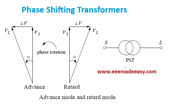
In the phase-advance mode, the voltage vector at the output of the PST is made to lead the input
voltage vector by adding a leading quadrature voltage to the source voltage.
In the phase-retard mode, a lagging quadrature voltage is added to the source voltage so that the voltage vector at the output of the PST lags the input voltage.
Normally, the phase shift can be varied during operation in definite steps by use of an OLTC. The sign of the phase shift can be inverted by using an OLTC having a reversing switch. These transformers can be constructed with many different winding configurations depending on the rated voltage, the
power output, and the amount of required phase shift.
the required maximum value of the phase shift angle decides the rating and size of the PST.
Depending on the voltage/power rating, phase shift angle requirements,
connected systems short-circuit capability and OLTC performance, two distinct
designs of PST are used, viz. single-core design and double-core design.The simpler single-core design is generally used at lower voltages for small phase shifts and small ratings of PSTs.
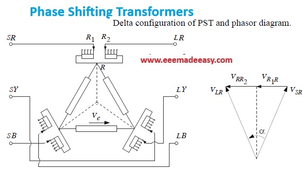
Figure shows the arrangement of a PST with a delta-connected exciting winding.
In this configuration, the regulating winding of each phase is wound on the same core
limb as the exciting winding.
The phase shift between the source (S) and load (L) terminals is achieved by connecting the regulating winding as shown in the figure. Its voltage is in phase with that of the exciting winding between the other
two phase terminals.
The voltage magnitudes of the S and L terminals are equal under the no-load condition. The phasor diagram shows the phase shift advancement obtained for the load terminal voltage with respect to the source terminal voltage.
If an OLTC with a reversing switch is used, one can obtain a phase-advance position as well as a phase-retard position.
The two-core design shown in Figure is popularly used for large PST ratings and phase shifts. This type of PST basically consists of a series unit and an exciting unit, which are enclosed in separate tanks. When the design is used for smaller ratings and lower voltages, both units can be enclosed in the same tank.
The winding of each phase of the series unit, between the source and load terminals, is split into two halves, and the main winding of the exciting unit is connected to the connection point of these two split windings.
The advantage of this arrangement is that the tap winding in the exciting unit and the winding a a’
in the series unit can be designed independently (the windings AA’ and BB’
form a part of the HV network). The voltage level of the tap winding and the
a a’ winding can be suitably chosen to reduce the tap changer cost.
In order to achieve rapid and smooth control of the power flow, static phase shifters can be used, which employ tap changers consisting of static devices like thyristors.
The calculation of currents in phase shifting transformers under system fault conditions requires more elaborate treatment as compared to that for conventional transformers.
Join EEE Made Easy Telegram channel
Join EEE Made Easy Whatsapp Channel
Books for All Competitive Exams
Read More on Transformer
- Transformers MCQ questions set 1
- Transformers MCQ Questions- Set 2
- Transformer MCQ Questions Set 3
- Efficiency of Transformer|Equation & Example
- Losses in a Transformer
- [Solved]Transformer Voltage Regulation Problem
- LVDT|Linear Variable Differential Transformer
- Autotransformer|Application of Autotransformer
- Transformers Electrical Engineering Interview Questions
- Why Transformers Hum: 7 Shocking Causes and Expert Solutions You Need to Know
- Single-phase transformer Connections Series & parallel
- Hysterisis and Eddy current losses