Planar transformer: The planar transformer, or inductor, is a low profile device that covers a large area, whereas, the conventional transformer would be more cubical in volume.
Planar Transformer
Planar Magnetics is the new “buzz” word in the field of power magnetics. It can be a way to increase the power density, while at the same time increasing the overall performance, and also, making it cost effective.
Read: Best Books for Transformer Design and Electrical Machine Design
A whole new learning curve can be seen on low profile ferrite cores and printed circuit boards if one is going to do any planar transformer designs.
It is an all-new technology for the transformer engineer. The two basic items that made this technology feasible were the power, MOSFETs that increased the switching frequency and enabled the designer to reduce the turns, and the ferrite core, which can be molded and machined into almost any shape.
Planar Transformer Basic Construction
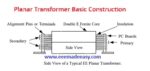
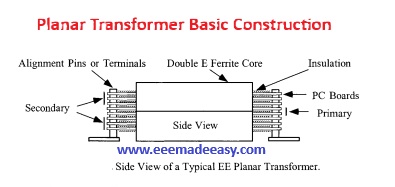
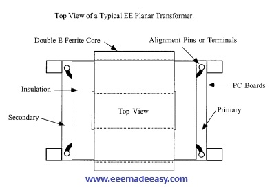
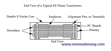
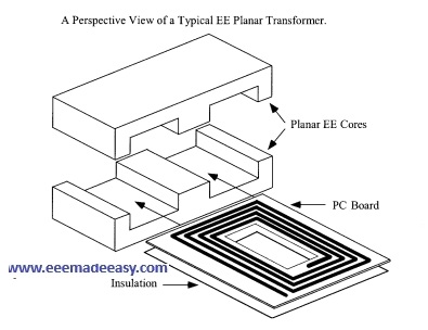
Here, shown in Figure 1 through Figure 4 are four views of a typical EE core, planar construction method.
The assembled planar transformers have very unique characteristics in their finished construction.
In the assembled planar transformer, every primary turn is at a precise location, governed by the PC board.
The primary is always the same distance from the secondary.
This provides a tight control over the primary to secondary leakage inductance. Using the same insulating material will always provide the same capacitance between primary and secondary; in this way, all parasitics will be the same from unit to unit.
With this type of planar construction, the engineer will have a tight control over leakage inductance, the
resonant frequency, and the common-mode rejection. A tight control is necessary on all materials used.
Planar Integrated PC Board Magnetics
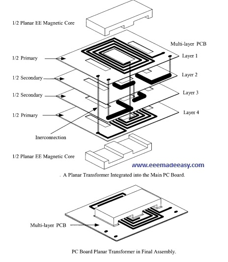
Planar transformers and inductors are now being integrated right on the main PC board. Design engineers
are pushing the operating frequency higher and higher to where it is commonplace to operate at frequency
range between 250-500kHz. As the frequency increases the power supplies are getting smaller and smaller.
To reduce the size of the power supply even further engineers are going to planar magnetics that are
integrated into the main PC board. An exploded view to show the multi-layers PC board of a planar
transformer that has been integrated into the main PC board is shown in Figure 20-5. The final assembly of
the same planar transformer is shown in Figure
Join EEE Made Easy Whatsapp Channel
Read More on Transformer
- Best Books for Transformer Design and Electrical Machine Design
- Transformers MCQ questions set 1
- Transformers MCQ Questions- Set 2
- Transformer MCQ Questions Set 3
- Efficiency of Transformer|Equation & Example
- Losses in a Transformer
- [Solved]Transformer Voltage Regulation Problem
- LVDT|Linear Variable Differential Transformer
- Autotransformer|Application of Autotransformer
- Transformers Electrical Engineering Interview Questions
- Why Transformers Hum: 7 Shocking Causes and Expert Solutions You Need to Know
- Single-phase transformer Connections Series & parallel
- Hysterisis and Eddy current losses
- Special Transformers
- Static Electrification in transformers
- Magnetostriction and its ill effects
Latest Posts in EEE Made Easy
- Planar Transformer
 Planar transformer: The planar transformer, or inductor, is a low profile device that covers a large area, whereas, the conventional … Read more
 - Best Books for Transformer Design and Electrical Machine DesignBest Books for Transformer Design and Electrical Machine Design: If you are studying Transformer Design, Electrical Machine Design or Design … Read more
- Transformers FundamentalsTransformers Fundamentals: Transformers are static devices that transfer electrical energy from one circuit toanother by the phenomenon of electromagnetic induction … Read more
- Transformer Tank Types|Classification of Transformer TanksTransformer Tank Types: Depending upon the position of the joint between the upper and lower parts, wehave two types of … Read more
- Static Electrification in transformersStatic Electrification in transformers: Generation of static charges, caused by oil streaming on a solid insulating component, is responsible for … Read more
- Special TransformersSpecial Transformers: There are some special transformers like Rectifier Transformers,Converter Transformers for HVDC,Furnace Transformers and Phase Shifting Transformer. Special Transformers … Read more
- Magnetostriction and its ill effectsMagnetostriction and Its ill-effects:The property of ferromagnetic materials, due to which their dimensions are changed due to change of magnetic … Read more