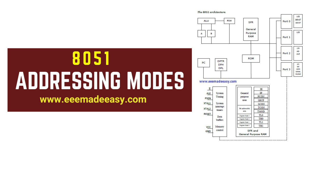
8051 Addressing Modes: The Addressing modes of 8051 Microcontroller are Immediate addressing Mode,Register addressing Mode,Direct addressing Mode,Indirect addressing Mode,Relative addressing Mode,Absolute addressing Mode,Long addressing Mode,Indexed addressing Mode,Bit inherent addressing Mode and Bit direct addressing Mode
In this post, you will learn What is called Addressing Mode? and the Addressing modes of 8051 Microcontroller. Lets start with the Instruction Syntax.
INSTRUCTION SYNTAX
Download & Install EEE Made Easy App
General syntax for 8051 assembly language is as follows.
LABEL: OPCODE OPERAND;COMMENT
LABEL : (THIS IS NOT NECESSARY UNLESS THAT SPECIFIC LINE HAS TO BE ADDRESSED).
The label is a symbolic address for the instruction.
When the program is assembled, the label will be given a specific address in which that instruction is stored.
Unless that specific line of instruction is needed by a branching instruction in the program, it is not necessary to label that line.
OPCODE: Opcode is the symbolic representation of the operation.
The assembler converts the opcode to a unique binary code (machine language).
OPERAND: While opcode specifies what operation to perform, operand specifies where to perform
that action.
The operand field generally contains the source and destination of the data.
In some cases only source or destination will be available instead of both.
The operand will be either address of the data, or data itself.
COMMENT: Always comment will begin with; or // symbol. To improve the program quality,
programmer may always use comments in the program.
2.8051 Microcontroller MCQ|8051 Questions and Answers
3. Addressing modes of 8051 Microcontroller|8051 Addressing Modes
4. 8051 Microcontroller Instruction Set|KSEB Sub Engineer Notes
ADDRESSING MODES 8051
What is Addressing Modes?
Various methods of accessing the data are called addressing modes.
8051 addressing modes are classified as follows.
- Immediate addressing Mode
- Register addressing Mode
- Direct addressing Mode
- Indirect addressing Mode
- Relative addressing Mode
- Absolute addressing Mode
- Long addressing Mode
- Indexed addressing Mode
- Bit inherent addressing Mode
- Bit direct addressing Mode
2. Microprocessors Vs Microcontrollers
1. Immediate addressing Mode
In this addressing mode the data is provided as a part of instruction itself. In other words
data immediately follows the instruction.
Eg. MOV A,#30H
ADD A, #83 # Symbol indicates the data is immediate.
2. Register addressing Mode
In this addressing mode the register will hold the data. One of the eight general registers
(R0 to R7) can be used and specified as the operand.
Eg. MOV A,R0
ADD A,R6
R0 – R7 will be selected from the current selection of register bank. The default register bank will be bank 0.
3. Direct addressing Mode
There are two ways to access the internal memory.
Using direct address and indirect address.
Using direct addressing mode we can not only address the internal memory but SFRs also.
In direct addressing, an 8 bit internal data memory address is specified as part of the instruction and hence, it can specify the address only in the range of 00H to FFH.
In this addressing mode, data is obtained directly from the memory.
Eg. MOV A,60h
ADD A,30h
4. Indirect Addressing Mode
The indirect addressing mode uses a register to hold the actual address that will be used in data
movement. Registers R0 and R1 and DPTR are the only registers that can be used as data pointers. Indirect
addressing cannot be used to refer to SFR registers. Both R0 and R1 can hold 8 bit address and DPTR can hold
16 bit address.
Eg. MOV A,@R0
ADD A,@R1
MOVX A,@DPTR
5. Indexed Addressing Mode
In indexed addressing, either the program counter (PC), or the data pointer (DTPR)—is
used to hold the base address, and the A is used to hold the offset address.
Adding the value of the base address to the value of the offset address forms the effective address.
Indexed addressing is used with JMP or MOVC instructions.
Look up tables are easily implemented with the help of index addressing.
Eg. MOVC A, @A+DPTR // copies the contents of memory location pointed by the sum of the
accumulator A and the DPTR into accumulator A.
MOVC A, @A+PC // copies the contents of memory location pointed by the sum of the
accumulator A and the program counter into accumulator A.
6. Relative Addressing Mode
Relative addressing is used only with conditional jump instructions.
The relative address, (offset), is an 8 bit signed number, which is automatically added to the PC to make the address of the next instruction.
The 8 bit signed offset value gives an address range of +127 to —128 locations.
The jump destination is usually specified using a label and the assembler calculates the jump offset accordingly.
The advantage of relative addressing is that the program code is easy to relocate and the address is relative to position in the memory.
Eg. SJMP LOOP1
JC BACK
7. Absolute Addressing Mode
Absolute addressing is used only by the AJMP (Absolute Jump) and ACALL (Absolute Call)
instructions.
These are 2 bytes instructions. The absolute addressing mode specifies the lowest 11
bit of the memory address as part of the instruction. The upper 5 bit of the destination address are
the upper 5 bit of the current program counter. Hence, absolute addressing allows branching only
within the current 2 Kbyte page of the program memory.
Eg. AJMP LOOP1
ACALL LOOP2
8. Long Addressing Mode
The long addressing mode is used with the instructions LJMP and LCALL. These are 3 byte
instructions. The address specifies a full 16 bit destination address so that a jump or a call can be
made to a location within a 64 Kbyte code memory space.
Eg. LJMP FINISH
LCALL DELAY
9. Bit Inherent Addressing Mode
In this addressing, the address of the flag which contains the operand, is implied in the opcode
of the instruction.
Eg. CLR C ; Clears the carry flag to 0
10. Bit Direct Addressing Mode
In this addressing mode the direct address of the bit is specified in the instruction.
The RAM space 20H to 2FH and most of the special function registers are bit addressable.
Bit address values are between 00H to 7FH.
Eg. CLR 07h ; Clears the bit 7 of 20h RAM space
SETB 07H ; Sets the bit 7 of 20H RAM space.
Read also: 1. 8051 Instruction Set
2. Microprocessors Vs Microcontrollers
Download & Install EEE Made Easy App
Read More on Microcontrollers
- Features of AVR|AVR Microcontrollers
- 8051 ARCHITECTURE|8051 Microcontroller Architecture
- 8051 Microcontroller Architecture|RISC and CISC CPU Architectures|HARVARD & VON- NEUMANN CPU Architecture
- Microprocessor VS Microcontroller| Comparison of Microprocessor and Microcontroller|Difference between Microprocessor and Microcontroller
- Addressing modes of 8051 Microcontroller|8051 Addressing Modes
- 8051 Microcontroller Instruction Set|KSEB Sub Engineer Notes
- 8051 Microcontroller MCQ|8051 Questions and Answers
- Microcontroller|Types of microcontroller
- 8051 Microcontroller Notes pdf|8051 microcontroller pdf
- Interrupts in 8051|Interrupts in 8051 Microcontroller
- Compensating Windings

- Transformers Electrical Engineering Interview Questions
- DC Motor Electrical Engineering Interview Questions
- Special Electrical Machines Interview Questions
- 125 Electrical Engineering Interview Questions
- Syllabus Training Instructor Plumber|14/2025 Syllabus Kerala PSC
- [PDF] Syllabus AE KSEB Transfer|378/2025 Syllabus Kerala PSC
- Modified Harvard Architecture
- TMS320C5X Architecture
- Advantages of Digital Signal Processing
- [PDF] AE Agro Industries Corporation syllabus|595/2024 syllabus Kerala PSC
- Tellengen’s Theorem & Example