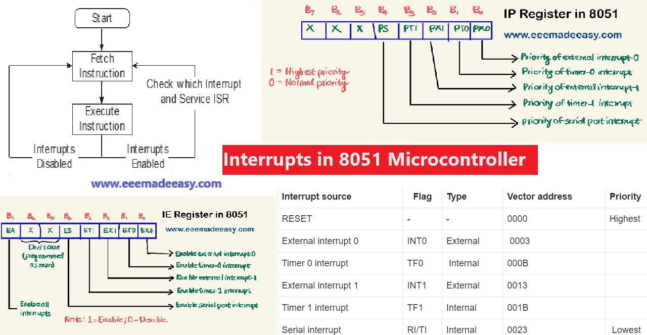
Interrupts in 8051: 8051 has 5 interrupt signals, i.e. INT0, TFO, INT1, TF1, RI/TI (excluding RESET). The highest priority interrupt in 8051 Microcontroller is the Reset, with vector address 0x0000.
In this post, Let’s Learn Interrupts in 8051, What is an interrupt in 8051 Microcontroller?, the Interrupt structure of 8051, and types of interrupts in 8051.
What is an interrupt in the 8051 Microcontroller?
Interrupts are nothing but an event that causes distraction from the currently going on process. Its like you are getting a phone call while you are busy with your work. If the call is important for you, then you may attend the call at that time. ie, based on priority the call will be answered.
Similarly, there are Interrupts in 8051 microcontroller, based on the priority of interrupts the program flow will continue.
During program execution, if peripheral devices need service from the microcontroller, the device will generate an interrupt and get the service from the microcontroller.
When a peripheral device activates the interrupt signal, the processor branches to a program called interrupt service routine.
After executing the interrupt service routine the processor returns to the main program.
8051Interrupt Process Steps
Steps taken by the processor while processing an interrupt:
- It completes the execution of the current instruction.
- PSW is pushed to stack.
- PC content is pushed to stack.
- Interrupt flag is reset.
- PC is loaded with ISR address.
ISR will always ends with RETI instruction. The execution of RETI instruction results in the
following.
- POP the current stack top to the PC.
- POP the current stack top to PSW.
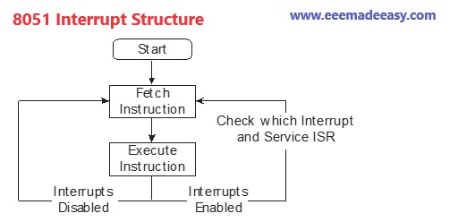
8051 Interrupt Structure
Types of interrupts in 8051
Classification of interrupts are given below
- External and internal interrupts.
- Maskable and non-maskable interrupts.
- Vectored and non-vectored interrupt.
External and internal interrupts
External interrupts are those initiated by peripheral devices through the external pins of
the microcontroller.
- 8051 has two external interrupt INT0 and INT1.
- 8051 controller can be interrupted by external Interrupt, by providing level or edge on external interrupt pins PORT3.2, PORT3.3.
Internal interrupts are those activated by the internal peripherals of the microcontroller
like timers, serial controller etc.
Maskable and non-maskable interrupts
The category of interrupts which can be disabled by the processor using program is called
maskable interrupts.
Non-maskable interrupts are those category by which the programmer cannot disable it
using program.
Vectored and non-vectored interrupts
The starting address of the ISR is called the interrupt vector.
In vectored interrupts, the starting address is predefined. In non-vectored interrupts, the starting address is provided by the peripheral as follows.
- The microcontroller receives an interrupt request from an external device.
- The controller sends an acknowledgment (INTA) after completing the execution of the current instruction.
- The peripheral device sends the interrupt vector to the microcontroller.
Read Also: 8051 Microcontroller Instruction Set
Download & Install EEE Made Easy App
8051 Interrupt Structure
8051 has five interrupts. They are maskable and vectored interrupts. Out of these five, two are
external interrupt and three are internal interrupts.
- Timer 0 overflow interrupt – TF0
- External hardware interrupt – INT0
- Timer 1 overflow interrupt – TF1
- External hardware interrupt – INT1
- Serial communication interrupt – RI/TI
8051 interrupt vector table
Vector Address is the address where the controller jumps after the interrupt to serve the ISR ie, Interrupt service routine.
The below table shows the 8051 Interrupt Priority Order.
Note: Among the 5 interrupts in 8051, INT0 is the highest priority interrupt; but when considering RESET as the interrupt, its the highest priority interrupt.
| Interrupt source | Flag | Type | Vector address | Priority |
|---|---|---|---|---|
| RESET | – | – | 0000 | Highest |
| External interrupt 0 | INT0 | External | 0003 | |
| Timer 0 interrupt | TF0 | Internal | 000B | |
| External interrupt 1 | INT1 | External | 0013 | |
| Timer 1 interrupt | TF1 | Internal | 001B | |
| Serial interrupt | RI/TI | Internal | 0023 | Lowest |
Read Also: 8051 Microcontroller Notes pdf
8051 Interrupt Registers
8051 makes use of two registers to deal with interrupts.
- IE Register (Interrupt Enable Register)
- IP Register(Interrupt Priority Register)
IE Register
Interrupt Enable Register is an 8-bit register used for enabling or disabling the interrupts.
The structure of IE register is shown below.
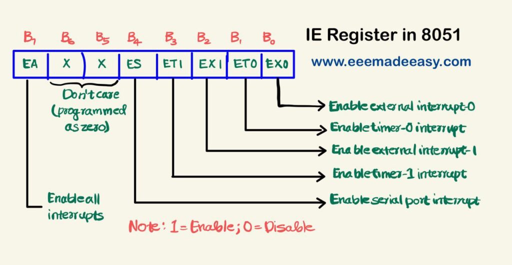
A bit corresponds to 1 activate the interrupt and 0 disable the interrupt.
Bit 7 – EA: Enable All Bit
1 = Enable all interrupts
0 = Disable all interrupts
Bit 6,5 – Reserved bits
Bit 4 – ES: Enable Serial Interrupt Bit
1 = Enable serial interrupt
0 = Disable serial interrupt
Bit 3 – ET1: Enable Timer1 Interrupt Bit
1 = Enable Timer1 interrupt
0 = Disable Timer1 interrupt
Bit 2 – EX1: Enable External1 Interrupt Bit
1 = Enable External1 interrupt
0 = Disable External1 interrupt
Bit 1 – ET0: Enable Timer0 Interrupt Bit
1 = Enable Timer0 interrupt
0 = Disable Timer0 interrupt
Bit 0 – EX0: Enable External0 Interrupt Bit
1 = Enable External0 interrupt
0 = Disable External0 interrupt
IP Register
Interrupt Priority Register is an 8-bit register used for setting the priority of the interrupts.
8051 has an interrupt priority register to assign priority to interrupts.
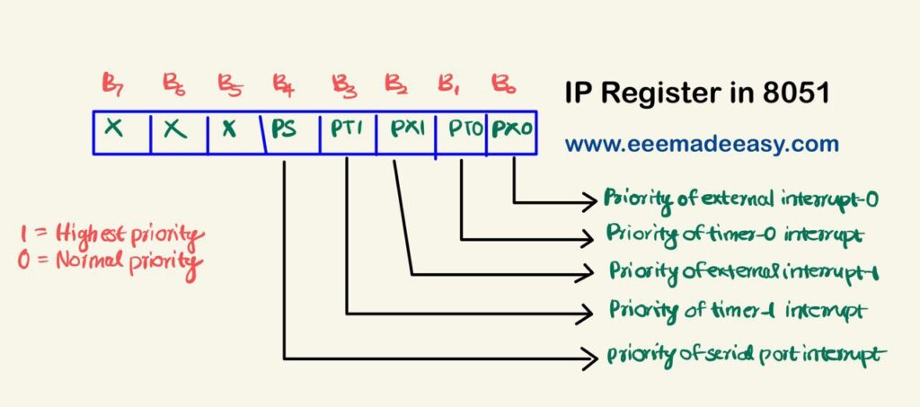
Interrupt Priority Register
Bit 7,6,5 – Reserved bits.
Bit 4 – PS: Serial Interrupt Priority Bit
1 = Assign a high priority to serial interrupt.
0 = Assign low priority to serial interrupt.
Bit 3 – PT1: Timer1 Interrupt Priority Bit
1 = Assign high priority to Timer1 interrupt.
0 = Assign low priority to Timer1 interrupt.
Bit 2 – PX1: External Interrupt 1 Priority Bit
1 = Assign high priority to External1 interrupt.
0 = Assign low priority to External1 interrupt.
Bit 1 – PT0: Timer0 Interrupt Priority Bit
1 = Assign high priority to Timer0 interrupt.
0 = Assign low priority to Timer0 interrupt.
Bit 0 – PX0: External0 Interrupt Priority Bit
1 = Assign high priority to External0 interrupt.
0 = Assign low priority to External0 interrupt.
Important Note on Interrrupt priority
- A low priority interrupt can only be interrupted by the high priority interrupt, but not interrupted by another low priority interrupt.
- If two interrupts of different priority levels are received simultaneously, the request of higher priority level is served.
- If the requests of the same priority levels are received simultaneously, then the internal polling sequence determines which request is to be serviced.
TCON Register
The TCON register specifies the type of external interrupt to the microcontroller.
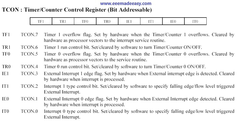
Timer Control or TCON Register is used to start or stop the Timers of 8051 Microcontroller.
TCON also contains bits to indicate if the Timers has overflowed.
The TCON Special Function Registers also consists of Interrupt related bits.
Books for Microcontroller 8051
- KSEB Sub Engineer and AE Books
- The 8051 Micro controller 3rd Edition,by Kenneth Ayala
- The 8051 Microcontrollers & Embedded Systems, by Mazidi
- 8051 MICROCONTROLLER AND APPLICATIONS FOR BSC
- Microcontroller & Embedded Systems for BE
Read More on Microcontroller
- Features of AVR|AVR Microcontrollers
- 8051 ARCHITECTURE|8051 Microcontroller Architecture
- 8051 Microcontroller Architecture|RISC and CISC CPU Architectures|HARVARD & VON- NEUMANN CPU Architecture
- Microprocessor VS Microcontroller| Comparison of Microprocessor and Microcontroller|Difference between Microprocessor and Microcontroller
- Addressing modes of 8051 Microcontroller|8051 Addressing Modes
- 8051 Microcontroller Instruction Set|KSEB Sub Engineer Notes
- 8051 Microcontroller MCQ|8051 Questions and Answers
- Microcontroller|Types of microcontroller
- 8051 Microcontroller Notes pdf|8051 microcontroller pdf
- Interrupts in 8051|Interrupts in 8051 Microcontroller
Latest Posts in EEE Made Easy
- [New] AE KWA Kerala PSC 2026AE KWA Kerala PSC 2026: DETAILED SYLLABUS FOR SELECTION TO THE POST OF ASSISTANT ENGINEER IN KERALA WATER AUTHOERITY AE … Read more
- [New] Electricity Worker KSEB Syllabus 2026|021/2026 Syllabus Kerala PSCElectricity Worker KSEB Syllabus 2026- 021/2026 Syllabus Kerala PSC: DETAILED SYLLABUS FOR THE POST OF ELECTRICITY WORKER IN KERALASTATE ELECTRICITY … Read more
- [Latest]KWA Operator Syllabus 2026|734,735/2025 Kerala PSC syllabusKWA Operator Syllabus 2026 – 734,735/2025 Kerala PSC syllabus: KERALA PUBLIC SERVICE COMMISSIONDETAILED SYLLABUS FOR THE POST OF OPERATOR (DIRECT) … Read more
- [New]Inspector of Legal Metrology Syllabus|613/2025 Kerala PSC SyllabusInspector of Legal Metrology Syllabus– 613/2025 Kerala PSC Syllabus: DETAILED SYLLABUS FOR THE POST OF INSPECTOR OF LEGAL METROLOGY IN … Read more
- [PDF]IE Rules|Indian Electricity Rules 1956
 IE Rules:The Indian Electricity Rules 1956 was made under section 37 of the Indian Electricity Act, 1910 and redefined after … Read more
 - [Latest]Syllabus Sub Engineer LSGD Electricity Wing Thrissur Corporation| 770/2025 Syllabus Kerala PSCSyllabus Sub Engineer LSGD Electricity Wing Thrissur Corporation: DETAILED SYLLABUS FOR THE POST OF SUB ENGINEER IN LSGD(ELECTRICITY WING OF … Read more
- Compensating WindingsCompensating Windings: Compensating Windings are used for large direct current machines which are subjected to large fluctuations in load i.e. … Read more