Three phase power measurement:The power consumed in a three-phase system is measured using wattmeters. Generally, one wattmeter is required for measuring power in one phase and hence three wattmeters would be required to measure power in a three-phase system. But, universally it is proved that only two wattmeters are enough to measure power in three-phase systems of any type i.e., balanced or unbalanced and star or delta-connected systems.
In addition, if the system is balanced, the circuit power factor can also be determined using the readings of two wattmeters.
Also, in a balanced system, the total power in all the three-phases can be obtained by multiplying the power obtained in a single-phase.
POWER MEASURMENT IN A THREE-PHASE SYSTEM
Wattmeter
A wattmeter is an instrument that is used to measure power in watts in a single-phase or a three-phase system.
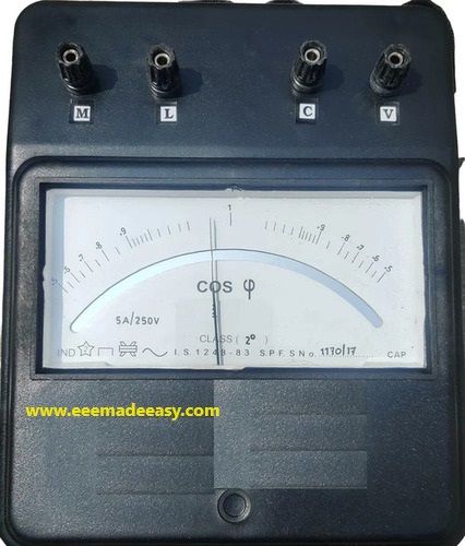
The two coils that exist in a wattmeter are: fixed or current coil and moving or pressure or voltage coil.
The wattmeter has four terminals: M, L, C and V; where ‘M’ is the terminal to which the phase voltage of supply or mains is connected, ‘L’ is the terminal to which the load is connected, ‘C’ is the common terminal in the wattmeter device and ‘V’ is the voltage terminal to connect the energy metre.
In a wattmeter, the terminals ‘M’ and ‘C’ are interconnected.
Fixed or Current Coil (CC)
The coil that is connected in series with the branch or line to sense the current flowing through it is called the current coil.
The characteristics of current coil are; low resistance, large cross-sectional area and less
number of turns.
The terminals, which are used to denote the CC, are M – L.
In a modern wattmeter, the maximum current that is allowed to pass through CC is 20 A.
Moving or Pressure or Voltage Coil (PC)
The high-resistance coils, which are connected across or parallel to the branch or line are called moving or pressure or voltage coils.
The two terminals of the pressure coil are ‘C’ and ‘V’, where the first one is the common terminal, which can be connected after or before the current coil and ‘V’ is the specified voltage terminal with actual voltage marking.
PC carries the current proportional to the voltage across the branch or line.
The characteristics of PC are: large resistance, small cross-sectional area and more number of turns.
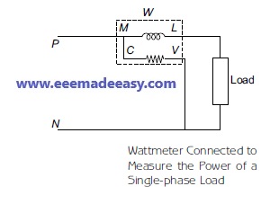
A wattmeter, which is connected to measure the power of a single-phase load, is shown in Figure below
In general, the power measured by the wattmeter is a product of voltage that the pressure
coil measures and the current that flows through the current coil.
Methods of Power Measurement
The three methods that are used for the measurement of three-phase power in three-phase circuits are:
- Three-Wattmeter Method
- Two-Wattmeter Method
- Single-Wattmeter Method
Blondel’s Theorem
When power is supplied by an ‘n’ wire AC system, then the number of wattmeters required to measure power is ‘n – 1’, i.e., one less than the number of wires in the AC system, irrespective of a balanced or an unbalanced load.
Therefore, for a three-phase four-wire system, the number of wattmeters required to measure the power is three and for a three-phase three-wire system, the number of wattmeters required to measure the power is two.
Three-Wattmeter Method
According to Blondel’s theorem, the three-wattmeter method can be used only to measure the power in threephase, four-wire star-connected balanced and unbalanced load, whose circuit diagram along with wattmeters W1, W2 and W3 is shown in Figures (a) and (b) respectively.
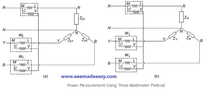
Balanced Load
Usually, the wattmeter connected across the balanced load measures the actual power measured by the load and is given by the product of root mean square (RMS) values of voltage and current.
The power consumed by the three-phase load, given in Figure (a) measured by W1, W2 and W3 are given by:
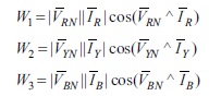

Therefore, the total power consumed by the load is given by
W = W1 + W2 + W3
Two-Wattmeter Method
measurement of three phase power by two wattmeter method
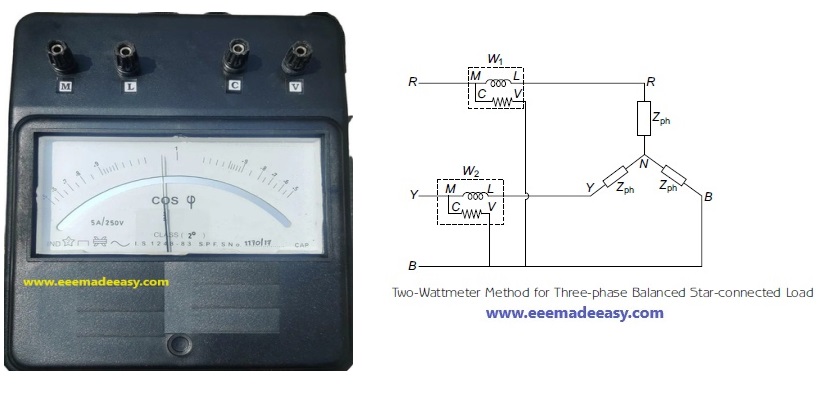
Two-wattmeter method is used to measure the total power in a three-phase, three-wire star or delta-connected balanced or unbalanced load.
In this method, the current coils of the wattmeter are connected with any two lines (i.e., R and Y) and the pressure coil of the wattmeter is connected between the above two lines and the
third line (i.e., B).
The different phase systems for which the two-wattmeter method can be used to measure
the power consumed by the load are:
- Star-connected balanced load
- Star-connected unbalanced load
- Delta-connected balanced load
- Delta-connected unbalanced load
Star-connected Balanced Load
The circuit diagram for two-wattmeter method applied to a three-phase balanced star-connected load is shown in Figure below.
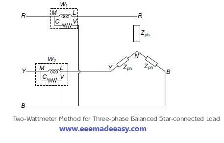
The two wattmeter method will be discussed in detail in another Post.
- [PDF]Electrical Measurements Measuring Instruments Study Notes PDF|EMMI Notes EEE Made Easy
- MCQ on Electrical Instruments
- Types of Errors in Instruments| Instrument Errors
- MCQ’s on Electrical Measuring Instruments|Instruments Objective Questions
- Electrical measuring instruments|Types of Measuring Instruments
- Static characteristics of instruments
- Types of measuring instruments- www.eeemadeeasy.com
- Moving Iron Instruments
- Instruments- Basics
- PMMC Instruments
- Types of instruments
- Essentials of Indicating instruments
- MCQ’s on Galvanometer|Galavnometer Questions & Answers
- MCQs on potentiometer|potentiometer Questions and answers
- TOD Meter or Time of Day Meter
- Light meters or illumination meter|Lux meter
- VU and decibel meters
- Multimeter- Principle and operation
- Digital readout meters-principle and operation
- Watt-hour meters- principle and operation
- Wattmeter -principle and working
- FET and vacuum-tube voltmeters
- Ohmmeter- basic principle and working
- Ammeters|Current Measurement
- Voltmeter- Principle and operation
- The household energy meter is
- Q Meter
- Thermistor| What is a Thermistor
- RTD vs Thermistor|Comparison between RTD and Thermistor
Latest Posts in EEE Made Easy
- 25 MCQs on 8051 Microcontroller- Set 225 MCQs on 8051 Microcontroller: In this post you can practice questions on 8051 Microcontroller. You can … Read more
- 25 MCQs on 8051 Microcontroller25 MCQs on 8051 Microcontroller: In this post you can practice questions on 8051 Microcontroller. You can … Read more
- Transformer MCQs – Set 3Transformer MCQs – Set 3: Here is another Transformer MCQs – Set 3. Set 1 & 2 … Read more
- 25 Transformer MCQs – Set 2Transformer MCQs – Set 2: Here is a new set of 25 questions, this set includes transformer … Read more
- 25 MCQs on Transformers25 MCQs on Transformers: set of 25 Transformer MCQs covering fundamentals, construction, EMF equation, losses, efficiency, voltage … Read more
- Basics of Transformer Ratings and KVA ratingBasics of Transformer Ratings and KVA rating: KVA Rating and Impedance Rating are two common transformer ratings. … Read more
- Satellite Altitude and Orbit Control( AOCS)
 Satellite Altitude and Orbit Control: In this post, Altitude Control & Orbit Control of Satellite is explained. … Read more