A Q meter measures the quality factor of a circuit Q, which expresses how much energy is dissipated per cycle in a non-ideal reactive circuit. A Q meter is used to measure the Q factor of a coil and related electrical properties.
Q meter
Q meteris based on the principle that Q factor of a resonant circuit is equal to its voltage magnification factor and can be expressed as the ratio of voltage developed across its reactive elements to the voltage injected in series with the circuit to produce the developed voltage.
Join EEE Made Easy Telegram channel
Quality factor (Q factor)
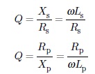
The quality factor (Q) of a coil is the ratio of reactance to resistance in a frequency dependent circuit configuration.
The Q factor or quality factor of an inductance is commonly expressed as the ratio of its series reactance to its series resistance.
For inductor in series or parallel, the ratio of reactance to resistance in a frequency dependent
circuit configuration is given by
The value of Q varies from 5 to 1000.
The Q factor of a capacitance is the ratio of its series reactance to its series resistance, lthough for capacitors, generally dissipation factor (D) is used which is the reciprocal of Q.
For capacitor in parallel or series, the ratio of reactance to resistance in a frequency dependent
circuit configuration is given by,
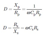
The value of D varies from 10-4 to 0.1
The basic circuit for a Q-meter is shown in Figure below.
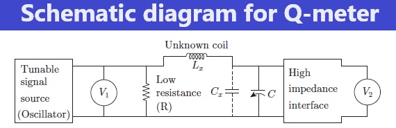
The circuit contains terminals for connecting the inductance (Lx ) to be measured and this is brought in resonance by a variable tuning capacitor (C).
There are terminals available for adding capacitance (Cx), if required.
When an unknown coil is connected to the test terminals, the circuit is excited by a tunable signal source.
This is achieved by setting the oscillator to a given frequency and varying the internal capacitor (C) or adding a capacitor Cx of the desired value and adjusting the frequency of the oscillator.
This leads to development of voltage across a resistor in series with the tuned circuit.
The resistance of the resistor should be very small (fractional in ohms) so that it can be neglected in comparison to the loss resistance of the components to be measured.
The AC injection voltage (V in) across the series resistor and the AC output voltage (V
out ) across the terminals of the tuning capacitor are measured using voltmeters.
The circuit for output measurement must be a high input impedance circuit so that loading of the tuned circuit by the metering circuit is prevented.
The Q-factor is measured by adjusting the source frequency and/or the tuning capacitor for a peak output voltage corresponding to resonance.
Q-factor is determined as the ratio of output voltage measured across the tuned circuit to voltage injected into it.
When Lx and Cx are at resonance:
Q = Vout/ Vin
The voltage across the variable capacitor is measured with electronic voltmeter V2 , in which the scale is calibrated to read Q directly.
Join EEE Made Easy Whatsapp Channel
- [PDF]Electrical Measurements Measuring Instruments Study Notes PDF|EMMI Notes EEE Made Easy
- MCQ on Electrical Instruments
- Types of Errors in Instruments| Instrument Errors
- MCQ’s on Electrical Measuring Instruments|Instruments Objective Questions
- Electrical measuring instruments|Types of Measuring Instruments
- Static characteristics of instruments
- Types of measuring instruments- www.eeemadeeasy.com
- Moving Iron Instruments
- Instruments- Basics
- PMMC Instruments
- Types of instruments
- Essentials of Indicating instruments
- MCQ’s on Galvanometer|Galavnometer Questions & Answers
- MCQs on potentiometer|potentiometer Questions and answers
- TOD Meter or Time of Day Meter
- Light meters or illumination meter|Lux meter
- VU and decibel meters
- Multimeter- Principle and operation
- Digital readout meters-principle and operation
- Watt-hour meters- principle and operation
- Wattmeter -principle and working
- FET and vacuum-tube voltmeters
- Ohmmeter- basic principle and working
- Ammeters|Current Measurement
- Voltmeter- Principle and operation
- The household energy meter is
- Q Meter
- Thermistor| What is a Thermistor
- RTD vs Thermistor|Comparison between RTD and Thermistor
Latest Posts in EEE Made Easy
- Compensating Windings
 Compensating Windings: Compensating Windings are used for large direct current machines which are subjected to large fluctuations in load i.e. … Read more
 - Transformers Electrical Engineering Interview QuestionsTransformers Electrical Engineering Interview Questions: QUESTIONS AND ANSWERS ON TRANSFORMERS Read: 125 Electrical Interview Questions Q.1. How is magnetic leakage … Read more
- DC Motor Electrical Engineering Interview QuestionsDC Motor Electrical Engineering Interview Questions: DC Motor Interview Questions and answers. Read: 125 Electrical Interview Questions Q. 1. How … Read more
- Special Electrical Machines Interview QuestionsSpecial Electrical Machines Interview Questions: Electrical Interview Questions Read: Electrical Interview Q.1. Do stepper motors have internal or external fans? … Read more
- 125 Electrical Engineering Interview QuestionsElectrical Engineering Interview Questions: Read 125 Questions based on Electrical Interview Questions. 1) What is Electrical Engineering? Electrical Engineering … Read more
- Syllabus Training Instructor Plumber|14/2025 Syllabus Kerala PSCSyllabus Training Instructor Plumber: 14/2025 Syllabus Kerala PSC. Download the syllabus and Previous question papers for the Training Instructor in … Read more
- [PDF] Syllabus AE KSEB Transfer|378/2025 Syllabus Kerala PSCSyllabus AE KSEB Transfer: DETAILED SYLLABUS FOR THE POST OF ASSISTANT ENGINEER(ELECTRICAL) (Kerala State Electricity Board Ltd.) – By Transfer … Read more
Latest Posts in EEE Made Easy
- Compensating WindingsCompensating Windings: Compensating Windings are used for large direct current machines which are subjected to large fluctuations in load i.e. … Read more
- Transformers Electrical Engineering Interview QuestionsTransformers Electrical Engineering Interview Questions: QUESTIONS AND ANSWERS ON TRANSFORMERS Read: 125 Electrical Interview Questions Q.1. How is magnetic leakage … Read more
- DC Motor Electrical Engineering Interview QuestionsDC Motor Electrical Engineering Interview Questions: DC Motor Interview Questions and answers. Read: 125 Electrical Interview Questions Q. 1. How … Read more
- Special Electrical Machines Interview QuestionsSpecial Electrical Machines Interview Questions: Electrical Interview Questions Read: Electrical Interview Q.1. Do stepper motors have internal or external fans? … Read more
- 125 Electrical Engineering Interview QuestionsElectrical Engineering Interview Questions: Read 125 Questions based on Electrical Interview Questions. 1) What is Electrical Engineering? Electrical Engineering … Read more
- Syllabus Training Instructor Plumber|14/2025 Syllabus Kerala PSCSyllabus Training Instructor Plumber: 14/2025 Syllabus Kerala PSC. Download the syllabus and Previous question papers for the Training Instructor in … Read more
- [PDF] Syllabus AE KSEB Transfer|378/2025 Syllabus Kerala PSCSyllabus AE KSEB Transfer: DETAILED SYLLABUS FOR THE POST OF ASSISTANT ENGINEER(ELECTRICAL) (Kerala State Electricity Board Ltd.) – By Transfer … Read more