DOL Starter or Direct on line Starter is a starting method used for Induction Motors. DOL Motor is also knows as “across the line starter”. Direct on line Starter is a device consisting of a main contactor, protective devices and overload relay which is used for motor starting operations. DOL Starter is used for low rating usually below 5HP motors.
Direct on line Starter
The schematic diagram of an induction motor with direct-on-line (DOL) starter is shown in Figure
dol starter diagram
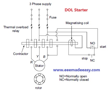
The main purpose of this starter is to protect the induction motor from different abnormal conditions like over-voltage, low voltage etc.
It is used in the induction motor whose capacity is less than 5 Horsepower.
Since the starting current in this capacity motor is less, a DOL starter applies rated voltage to the stator winding.
The normal open and normal close contacts in a DOL starter represent the normally open switch and normally closed switch.
These contacts are used to start and stop the induction motor respectively.
A small cage induction motor may be switched \direct-on-line,” meaning that it is switched directly onto normal voltage, momentarily taking several times the full-load current at a low power factor.
Direct switching may be the subject of Supply Authority regulations. However, there is usually no restriction on small induction motors up to 5.5 kW.
The various starters which are employed to restrict the initial rush of current in squirrel cage induction motors are Direct On Line (D.O.L.) Starter, Primary resistance (or inductance) starter, Star/Delta Starter, and Auto-transformer Starter.
Direct on Line (D.O.L.) Starter It is a starter by which the motor is switched ON direct to the supply mains by switching conductor.
With normal industrial motors this operation results in a heavy rush of current of the order of five to seven times of the normal full load current.
This high current rapidly decreases as the motor picks up speed but it is at a very low power factor and thus tends to disturb the voltage of the supply in the distribution lines.
For this reason, the supply authorities limit the size of motor upto 5 H.P. which can be started by this starter.
Automatic DOL starter diagram
An automatic D.O.L. Starter is shown in Fig.
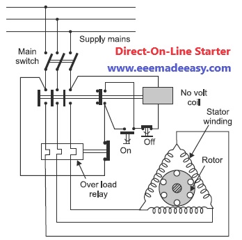
A direct on line starter essentially consists of a contactor having four normally open (N.O.) contacts and a contactor coil also known as no-volt coil or no volt release.
There are two push buttons ON and OFF which are used to start and stop the motor.
To protect motor against overload, thermal or magnetic over-load coils are connected in each phase.
To start the motor, the ON push button (green) is pressed which energies the no-volt coil by
connecting it across two phases.
The no-volt coil pulls its plunger in such a direction that all the normally open (NO) contacts are closed and motor is connected across supply through three contacts.
The fourth contact serves as a hold on contact which keeps the no-volt coil circuit closed even after the ON push button is released.
To stop the motor, OFF push button (red) is pressed momentarily which de-energises the no volt coil opening the main contacts.
When the motor is over loaded, the thermal overload relay contact, connected in the control
circuit opens thus disconnecting the No-volt relay from the supply.
Overload protection is achieved by thermal element overload relay.
Torque developed by the motor when started by direct on line starter:
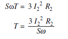
Power developed in the rotor or rotor input = wT
Rotor copper loss = S x rotor input
= SwT
Also rotor copper loss = 3 I22 R2
Where S is the slip, is the angular velocity, T is the torque developed, I2 is the rotor current per
phase and R2 is the rotor resistance per phase.
Equating the eqn. (i) and (ii), we get,

since rotor resistance and supply frequency is constant.
As stator current is proportional to rotor current,
i.e.,
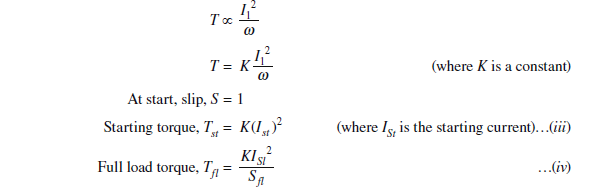
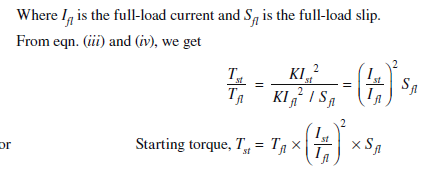
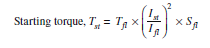
When motor is connected to the mains by direct on line starter, the starting current of the motor
will be equal to the short-circuit current Isc
Read more on DC Machines
- Armature Reaction MCQ|DC Generator MCQ Questions|DC machines
- Compensating Windings
- DC Machines Questions and Answers|DC Machines MCQ
- D.C Machines|What is a DC machine
- Armature Reaction in DC Machines|Cross Magnetization and Demagnetization
- 50 MCQ questions on DC Motor|Electrical Machines MCQ Questions and answers|DC Motor MCQ
- MCQs on DC Motor Tests|Tests on DC Motor Objective Questions
- Speed Control of D.C Motor MCQ Questions|Objective Questions on DC Motor Speed Control
- DC motor objective questions for Industrial extension officer ssc JE Electrical
- Speed Control of DC Motor|Shunt, Series, Compound DC Motor Speed control
- Efficiency of DC Motors with Example
Latest Posts in EEE Made Easy
- 25 MCQs on 8051 Microcontroller- Set 225 MCQs on 8051 Microcontroller: In this post you can practice questions on 8051 Microcontroller. You can … Read more
- 25 MCQs on 8051 Microcontroller25 MCQs on 8051 Microcontroller: In this post you can practice questions on 8051 Microcontroller. You can … Read more
- Transformer MCQs – Set 3Transformer MCQs – Set 3: Here is another Transformer MCQs – Set 3. Set 1 & 2 … Read more
- 25 Transformer MCQs – Set 2Transformer MCQs – Set 2: Here is a new set of 25 questions, this set includes transformer … Read more
- 25 MCQs on Transformers25 MCQs on Transformers: set of 25 Transformer MCQs covering fundamentals, construction, EMF equation, losses, efficiency, voltage … Read more
- Basics of Transformer Ratings and KVA ratingBasics of Transformer Ratings and KVA rating: KVA Rating and Impedance Rating are two common transformer ratings. … Read more
- Satellite Altitude and Orbit Control( AOCS)
 Satellite Altitude and Orbit Control: In this post, Altitude Control & Orbit Control of Satellite is explained. … Read more