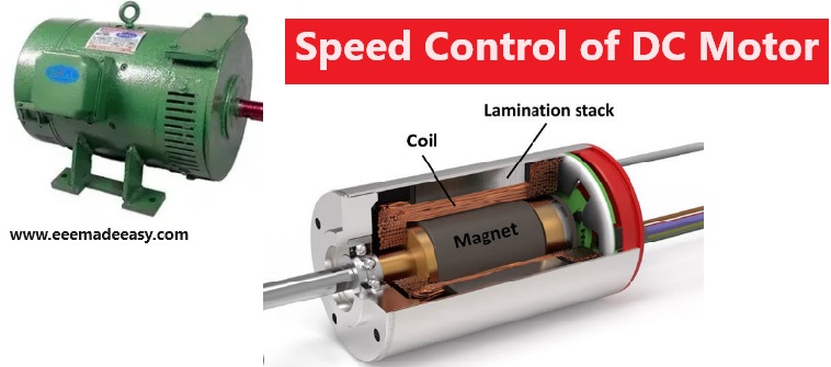
Speed Control of DC Motor: The process of intentionally changing the drive speed of DC Motor is called Speed control of DC Motor. The DC Motor speed can be cotrolled manually or using an automatic control device.
Download & Install EEE Made Easy App
Speed Control of DC Motor
The speed equation of a DC motor is given by,
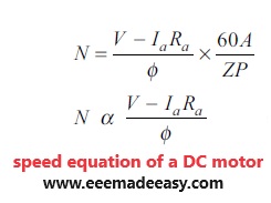
From the above equation, it is concluded that the speed of a DC motor can be controlled by the following methods:
● Armature resistance control method: Here, the armature resistance of DC motor is varied to control the speed.
● Flux control method: Here, varying the flux produced by the poles controls the speed of the DC motor.
● Applied voltage: Here, varying the excitation voltage given to the armature and field windings controls the speed of the DC motor.
Join EEE Made Easy Telegram channel
Speed Control of DC Shunt Motor
Flux control Method
The circuit diagram of flux control method to control the speed of a DC shunt motor is shown in Figure given below.
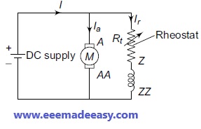
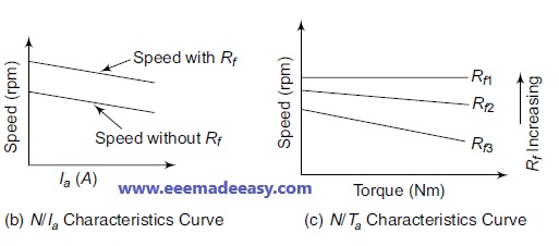
Flux control Method is used to control the speed of a DC shunt motor above the rated speed, by reducing the field flux.
In Flux control Method of speed control, a variable resistance element called shunt field rheostat is connected in series with the shunt-field winding, which helps in reducing the flux and the field current.
Since the field Ohmic loss is very small, this method is frequently used. Also, it is very simple and economic.
The N/Ia characteristics and N/Ta characteristics are shown in Figures given below.
Armature Resistance Control Method
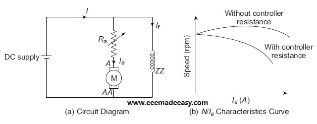
In Armature Resistance Control Method, including a resistance in series with Ra controls the speed of a DC shunt motor, as shown in Figure given below.
This method is used to vary the speed of a DC shunt motor, below the rated speed since
N ∝ V – IaRa i.e., the inclusion of resistance in series with Ra reduces the armature current, which further reduces the speed of a DC shunt motor.
The N/Ia characteristics of a DC shunt motor with and without the extra resistance are shown in Figure below.
Voltage Control Method
The different voltage control methods used for controlling the speed of a DC shunt motor are:
● Multiple voltage control
● Ward–Leonard system
Multiple Voltage Control
In this method, a suitable arrangement is made in such a way that the field winding gets a constant supply voltage and armature winding gets a variable voltage.
The different voltages that can be used for exciting armature winding are obtained using a switch-gear.
Since the speed of the motor is directly proportional to the supply voltage applied to the armature, varying the voltage applied to the armature can control the speed.
Ward–Leonard System
The arrangement of Ward–Leonard system to control the speed of a DC shunt motor is shown in Figure given below.
Here, M2 is the DC shunt motor whose speed has to be controlled, M1 can be either AC or DC motor with constant speed, which is coupled directly to generator G.
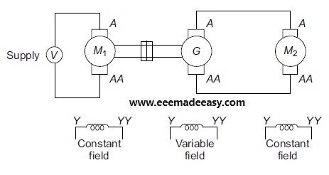
As shown in Figure given above, the output of G1 is fed as the input to the armature of motor M2.
The field winding of M2 is given by a constant DC supply voltage.
Therefore, varying the generator output can vary the supply voltage applied to armature of M2.
The generator output can be varied using a field regulator.
Thereby, a very smooth speed control of DC shunt motor can be obtained using this method.
This method is used in applications where very sensitive speed control is required.
For example, elevators, electric excavators etc.
Speed Control of a DC Series Motor
Flux Control Method
The different methods in which the flux produced by the field windings can be varied, thereby controlling the speed of DC series motor, are:
- Field diverter method
- Armature diverter method
- Tapped-field control method and
- Paralleling field coils
Field Diverter Method
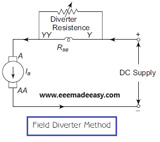
The circuit diagram for this method is shown in Figure above.
In this method, a field diverter or a variable resistance is connected in parallel to the series field windings of a DC series motor.
This field diverter is used to reduce the line current flowing through the series field windings.
Since the field current is getting decreased, the flux developed by the poles gets lowered, which increases the speed of the motor.
Using this method, the speed of a DC motor above rated speed can be obtained.
Armature Diverter Method
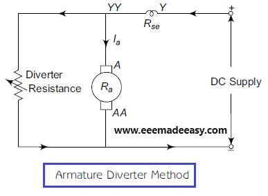
Using this method, the speed of a DC series motor below the rated speed can be obtained.
This method uses armature diverter to reduce the current flowing through the armature, as shown in Figure above.
By varying this armature diverter, the speed control of a DC series motor can be achieved.
Tapped-field Control Method
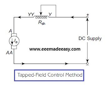
The difference between the field diverter method and the tapped field control method is that tapped-field windings are used in the tapped field control method, whereas a field diverter is used in the field diverter method.
The circuit diagram of tapped-field control method is shown in the above Figure.
The switch S is used to create a connection to the desired point in the tapped-field winding.
Here, by reducing the number of turns in the field winding reduces the field flux, which in turn
increases the speed of the DC series motor.
Similar to field diverter method, this method can be used to control the speed
above the rated speed of the DC series motor.
Paralleling Field Coils
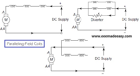
In this method, a single series field winding is divided into number of parts and these sub-coils are arranged in any one way, as shown in Figure above, to reduce the flux produced by the field winding, thereby increasing the speed of the DC series motor.
Armature Resistance Control Method
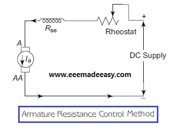
The circuit diagram for the speed control of a DC series motor, by varying armature resistance, is shown in Figure.
In Armature resistance control method, an adjustable resistor is connected in series with the
source voltage to control the speed of a DC series motor below the rated speed.
Read more on DC Machines
- Armature Reaction MCQ|DC Generator MCQ Questions|DC machines
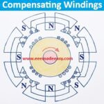
- Compensating Windings
- DC Machines Questions and Answers|DC Machines MCQ
- D.C Machines|What is a DC machine
- Armature Reaction in DC Machines|Cross Magnetization and Demagnetization
- 50 MCQ questions on DC Motor|Electrical Machines MCQ Questions and answers|DC Motor MCQ
- MCQs on DC Motor Tests|Tests on DC Motor Objective Questions
- Speed Control of D.C Motor MCQ Questions|Objective Questions on DC Motor Speed Control
- DC motor objective questions for Industrial extension officer ssc JE Electrical
- Speed Control of DC Motor|Shunt, Series, Compound DC Motor Speed control
- Efficiency of DC Motors with Example
Latest Posts on EEE Made Easy
Latest Posts in EEE Made Easy
- [New] AE KWA Kerala PSC 2026AE KWA Kerala PSC 2026: DETAILED SYLLABUS FOR SELECTION TO THE POST OF ASSISTANT ENGINEER IN KERALA WATER AUTHOERITY AE … Read more
- [New] Electricity Worker KSEB Syllabus 2026|021/2026 Syllabus Kerala PSCElectricity Worker KSEB Syllabus 2026- 021/2026 Syllabus Kerala PSC: DETAILED SYLLABUS FOR THE POST OF ELECTRICITY WORKER IN KERALASTATE ELECTRICITY … Read more
- [Latest]KWA Operator Syllabus 2026|734,735/2025 Kerala PSC syllabusKWA Operator Syllabus 2026 – 734,735/2025 Kerala PSC syllabus: KERALA PUBLIC SERVICE COMMISSIONDETAILED SYLLABUS FOR THE POST OF OPERATOR (DIRECT) … Read more
- [New]Inspector of Legal Metrology Syllabus|613/2025 Kerala PSC SyllabusInspector of Legal Metrology Syllabus– 613/2025 Kerala PSC Syllabus: DETAILED SYLLABUS FOR THE POST OF INSPECTOR OF LEGAL METROLOGY IN … Read more
- [PDF]IE Rules|Indian Electricity Rules 1956
 IE Rules:The Indian Electricity Rules 1956 was made under section 37 of the Indian Electricity Act, 1910 and redefined after … Read more
 - [Latest]Syllabus Sub Engineer LSGD Electricity Wing Thrissur Corporation| 770/2025 Syllabus Kerala PSCSyllabus Sub Engineer LSGD Electricity Wing Thrissur Corporation: DETAILED SYLLABUS FOR THE POST OF SUB ENGINEER IN LSGD(ELECTRICITY WING OF … Read more
- Compensating WindingsCompensating Windings: Compensating Windings are used for large direct current machines which are subjected to large fluctuations in load i.e. … Read more