Armature Reaction

Armature reaction is the effect of a magnetic field set up by armature current on the distribution of flux under the main poles of a generator.
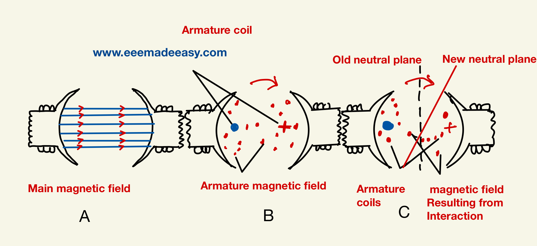
The armature magnetic field has two effects :
(i) It demagnetizes or weakens the main flux and
(ii) It cross-magnetizes or distorts it.
The demagnetizing effect leads to reduced generated voltage and the cross magnetizing effect to the sparking at the brushes.
Armature Reaction MCQ|DC Generator MCQ Questions|DC machines
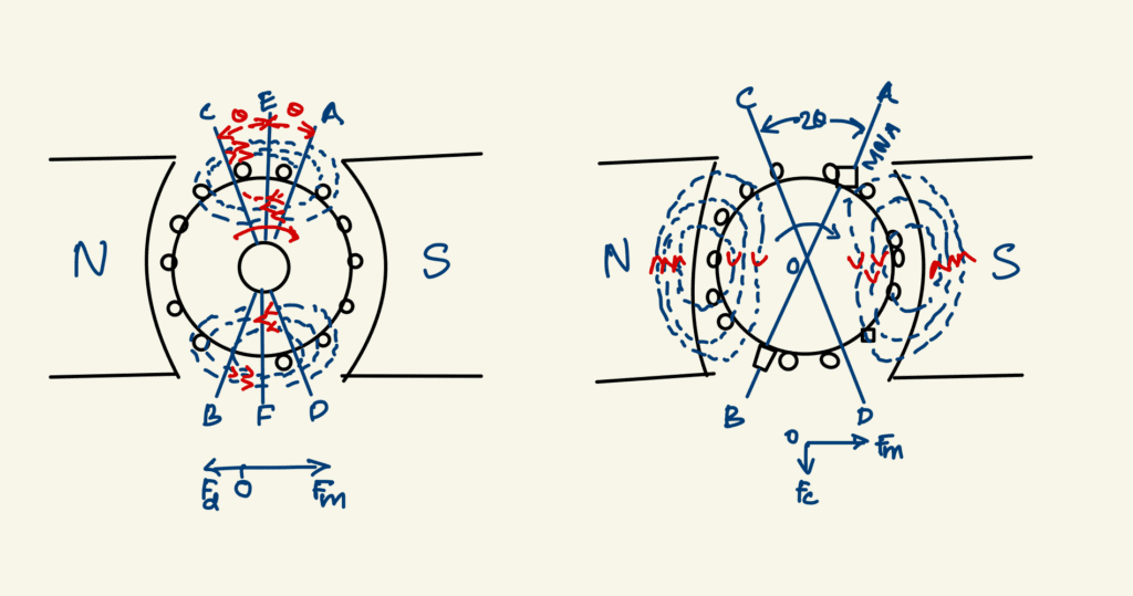
The fig below shows the flux distribution of a bipolar generator when there is no current in the armature conductors.
It is seen that
(a) the flux is distributed symmetrically with respect to the polar axis, which is the line joining the centres of NS poles.
(b) The magnetic neutral axis or plane (M.N.A.) coincides with the geometrical neutral axis or plane (G.N.A.)
Magnetic neutral axis
The magnetic neutral axis may be defined as the axis along which no e.m.f. is produced in the armature conductors because they then move parallel to the lines of flux.
Or M.N.A. is the axis which is perpendicular to the flux passing through the armature.
Axis of commutation’
brushes are always placed along M.N.A. Hence, M.N.A. is also called ‘axis of commutation’ because reversal of current in armature conductors takes place across this axis.
So far, we considered the main m.m.f. and armature m.m.f. separately as if they existed independently, which is not the case in practice. Under actual load conditions, the two exist simultaneously in the generator as shown.
It is seen that the flux through the armature is no longer uniform and symmetrical about the pole axis, rather it has been distorted.
The flux is seen to be crowded at the trailing pole tips but weakened or thinned out at the leading pole tips (the pole tip which is first met during rotation by armature conductors is known as the leading pole tip and the other as trailing pole tip).
It should be noted that both distorting and demagnetizing effects will increase with the increase in the armature current.
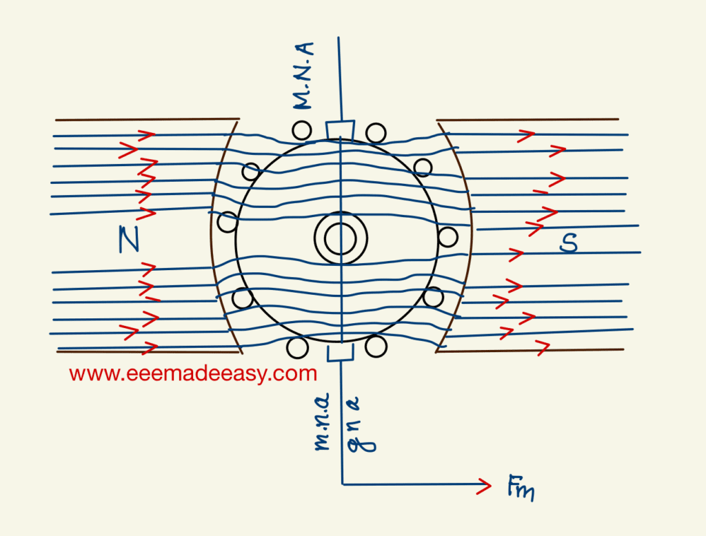
Demagnetising and Cross-magnetising Conductors
The exact conductors which produce these distorting and demagnetizing effects are shown in above Fig. where the brush axis has been given a forward lead of θ so as to lie along the new position of M.N.A. All conductors lying within angles AOC = BOD = 2θ at the top and bottom of the armature, are carrying current in such a direction as to send the flux through the armature from right to left.
This fact may be checked by applying crockscrew rule.
It is these conductors which act in direct opposition to the main field and are hence called the demagnetizing armature conductors.
Now consider the remaining armature conductors lying between angles AOD and COB.
As shown in Fig., these conductors carry current in such a direction as to produce a combined flux
pointing vertically downwards i.e. at right angles to the main flux.
This results in distortion of the main field. Hence, these conductors are known as cross-magnetizing conductors and constitute distorting ampere-conductors.
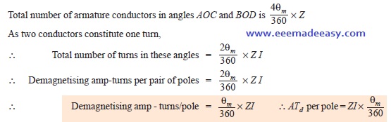
Demagnetising AT per Pole
Since armature demagnetizing ampere-turns are neutralized by adding extra ampere-turns to the main field winding, it is essential to calculate their number.
It should be remembered that the number of turns is equal to half the number of conductors because two conductors-constitute one turn.
Let Z = total number of armature conductors
I = current in each armature conductor
= Ia/2 … for simplex wave winding
= Ia/P … for simplex lap winding
θm = forward lead in mechanical or geometrical or angular degrees.
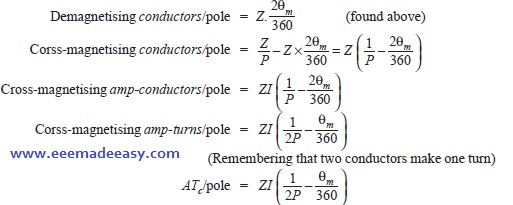
Cross-magnetising AT per pole
The conductors lying between angles AOD and BOC constitute what are known as distorting or cross-magnetising conductors.
Their number is found as under :
Total armature-conductors/pole both cross and demagnetising = Z / P
Note. (i) For neutralizing the demagnetizing effect of the armature reaction, an extra number of turns ay be put on each pole.
for shunt generator,
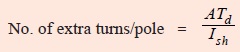
and for series generator, No of Extra turns per pole is

If the leakage coefficient λ is given, then multiply each of the above expressions by it.
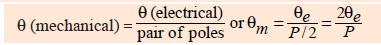
(ii) If lead angle is given in electrical degrees, it should be converted into mechanical degrees by the following relation.
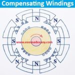
Compensating Windings
Compensating Windings are used for large direct current machines which are subjected to large fluctuations in load i.e. rolling mill motors and turbo-generators etc.
Their function is to neutralize the cross-magnetizing effect of the armature reaction.
In the absence of compensating windings, the flux will be suddenly shifting backward and forward with every change in load.
This shifting of flux will induce statically induced e.m.f. in the armature coils.
The magnitude of this e.m.f. will depend upon the rapidity of changes in load and the amount of change.
It may be so high as to strike an arc between the consecutive commutator segments across the top of the mica sheets separating them.
This may further develop into a flashover around the whole commutator thereby shortcircuiting the whole armature.
These windings are embedded in slots in the pole shoes and are connected in series with armature in such a way that the current in them flows in opposite direction to that flowing in armature conductors directly below the pole shoes.
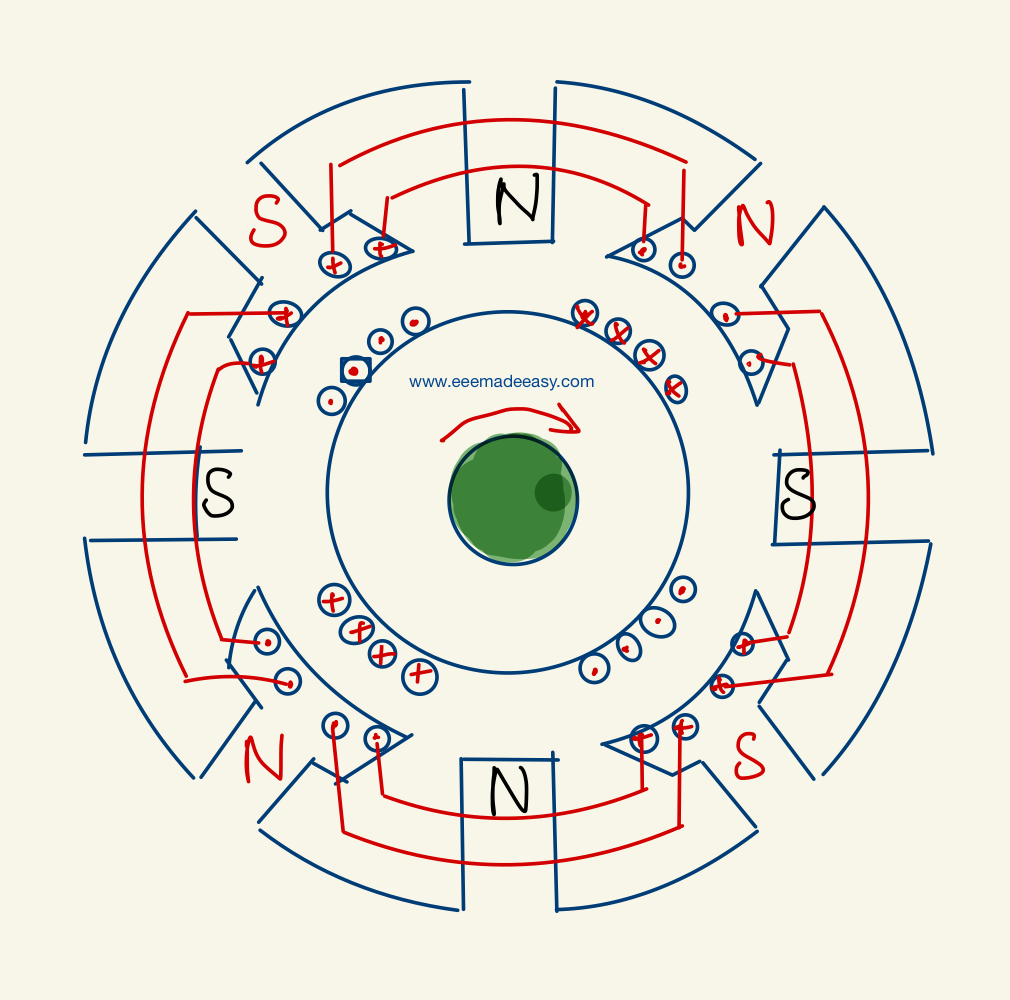
An elementary scheme of compensating winding is shown in aboveFig. compensating winding must provide sufficient m.m.f so as to counterbalance the armature m.m.f. Let
Zc = No. of compensating conductos/pole face
Za = No. of active armature conductors/pole,
Ia = Total armature current
Ia/A = current/armature conductor
∴ ZcIa = Za (Ia/A) or Zc = Za/A
Owing to their cost and the room taken up by them, the compensating windings are used in the case of large machines which are subject to violent fluctuations in load and also for generators that have to deliver their full-load output at considerable low induced voltage as in the Ward-Leonard set.
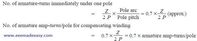
No. of Compensating Windings
No. of armature conductors/pole = Z/P
No. of armature turns/pole = 2Z/P
No. of armature-turns immediately under one pole is,
What is meant by armature reaction?
It is the effect of armature magnetic field on the distribution of flux under main poles of a generator.
What are the effects of armature reaction?
Cross Magnetization and Demagnetisation
What is the effect of Cross Magnetization?
cross magnetizing effect causes sparking at the brushes
What is the effect of Demagnetization?
reduce generated voltage
What is the effect of this distortion on the operation of the machine?
It acts as a magnetic drag on the armature which consequently requires more power to turn it.
How can field distortion be remedied?
By using compensating windings which are embedded in the slots in the pole shoe and are connected in series with the armature
What are the two types of armature reaction?
Cross Magnetization and Demagnetisation
Why is armature reaction?
The current flowing through the armature conductors creates a magnetic field, and this armature flux distorts or weakens the magnetic flux produced by the main poles. This effect of armature flux on the main flux is known as the armature reaction
What is the armature reaction formula?
What are the main effects of armature reaction?
How to reduce Armature reaction?
By using Compensating winding
Armature reaction is due to the presence of armature flux. Armature flux is produced due to the current flowing in armature conductors.
if we place another winding in close proximity of the armature winding and if it carries the same current but in the opposite direction as that of the armature current, then this will nullify the armature field.
That additional winding is called as compensating winding and it is placed on the pole faces.
Compensating winding is connected in series with the armature winding in such a way that it carries the current in opposite direction
Interpoles:Interpoles are the small auxiliary poles placed between the main field poles. Winding on the interpoles is connected in series with the armature. Each interpole is wound in such a way that its magnetic polarity is same as that of the main pole ahead of it. Interpoles nullify the quadrature axis armature flux.
- Armature Reaction MCQ|DC Generator MCQ Questions|DC machines
- 50 MCQ questions on DC Motor|Electrical Machines MCQ Questions and answers
/
Electrical Machines Best Books
| Sl no. | Book Title | Author | Buy Link |
|---|---|---|---|
| 1 | Textbook Of Electrical Technology : Ac And Dc Machines (volume – 2) | B L Theraja, AK Theraja | check price |
| 2 | Theory & Performance of Electrical Machines | J.B. Gupta | check price |
| 3 | Electrical Machines | by V.K Mehta, Rohit Mehta | check price |
| 4 | Electric Machines | PS Bimbhra | check price |
| 5 | Electrical Machines | S.K. Bhattacharya | check price |
- [New] AE KWA Kerala PSC 2026
- [New] Electricity Worker KSEB Syllabus 2026|021/2026 Syllabus Kerala PSC
- [Latest]KWA Operator Syllabus 2026|734,735/2025 Kerala PSC syllabus
- [New]Inspector of Legal Metrology Syllabus|613/2025 Kerala PSC Syllabus
- [PDF]IE Rules|Indian Electricity Rules 1956

- [Latest]Syllabus Sub Engineer LSGD Electricity Wing Thrissur Corporation| 770/2025 Syllabus Kerala PSC
- Compensating Windings
- Transformers Electrical Engineering Interview Questions
- DC Motor Electrical Engineering Interview Questions
- Special Electrical Machines Interview Questions
- 125 Electrical Engineering Interview Questions
- Syllabus Training Instructor Plumber|14/2025 Syllabus Kerala PSC