Square Wave Generation Using PIC16F877: In this post ,the methods of square wave generation using PIC16F877 Micro controller is explained. The applications of square wave also listed. Programming of PIC16F877 for sqaure wave generation also can be read in another post, will link it HERE.
Methods of square wave generation
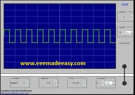
A square wave is a periodic waveform that alternates between two voltage levels (logic HIGH and LOW) with a 50% duty cycle in the simplest case. It is widely used in clock signals, digital timing, switching circuits, and waveform generation.
The PIC16F877 microcontroller can generate a square wave using two main approaches:
- Software delay method – toggling an I/O pin in a loop with delay routines.
- Hardware timer/PWM method – using on-chip timers and CCP (Capture/Compare/PWM) modules for accurate waveform generation.
(a) Software Delay Method
• Any digital output pin (e.g., RB0) can be set HIGH and LOW alternately in program code.
• Delays are introduced between transitions to control frequency.
• Simple, but frequency depends on instruction execution time and is less precise.
Frequency formula:
f=12⋅Tdelayf = \frac{1}{2 \cdot T_{delay}}f=2⋅Tdelay1
where TdelayT_{delay}Tdelay is the software delay used.
(b) Timer-Based Method
• PIC16F877 has Timer0, Timer1, and Timer2 which can generate periodic interrupts.
• The interrupt service routine (ISR) toggles an output pin → square wave output.
• This method gives better accuracy compared to software delays, since timers run with the oscillator clock.
Half-period time:
Thalf=(Prescaler×(256−TMRx_preload))×TcyT_{half} = (Prescaler \times (256 – TMRx_preload)) \times T_{cy}Thalf=(Prescaler×(256−TMRx_preload))×Tcy
where Tcy=4FoscT_{cy} = \frac{4}{F_{osc}}Tcy=Fosc4.
(c) PWM Using CCP Module
• The CCP (Capture/Compare/PWM) module can directly generate a square wave on CCP1 pin (RC2).
• By setting duty cycle to 50%, a symmetric square wave is obtained.
• Frequency is controlled by Timer2 and PR2 register.
PWM frequency formula:
fPWM=Fosc4⋅N⋅(PR2+1)f_{PWM} = \frac{F_{osc}}{4 \cdot N \cdot (PR2+1)}fPWM=4⋅N⋅(PR2+1)Fosc
where
• FoscF_{osc}Fosc = oscillator frequency,
• NNN = Timer2 prescaler,
• PR2 = period register.
Applications of Square Wave Using PIC16F877
• Generating clock pulses for other circuits.
• Driving stepper motors and DC motors (PWM speed control).
• Producing tones in buzzers.
• Carrier signal generation in communication.
• Timing and synchronization in embedded systems.
Advantages of Using PIC for Square Wave
• Multiple frequency ranges (software, timer, PWM).
• High accuracy with hardware timers.
• Minimal CPU load when using CCP PWM.
• Easy frequency adjustment via register values.
Read Also on PIC PIC16F877
More on Microcontrollers
- Features of AVR|AVR Microcontrollers
- 8051 ARCHITECTURE|8051 Microcontroller Architecture
- 8051 Microcontroller Architecture|RISC and CISC CPU Architectures|HARVARD & VON- NEUMANN CPU Architecture
- Microprocessor VS Microcontroller| Comparison of Microprocessor and Microcontroller|Difference between Microprocessor and Microcontroller
- Addressing modes of 8051 Microcontroller|8051 Addressing Modes
- 8051 Microcontroller Instruction Set|KSEB Sub Engineer Notes
- 8051 Microcontroller MCQ|8051 Questions and Answers
- Microcontroller|Types of microcontroller
- 8051 Microcontroller Notes pdf|8051 microcontroller pdf
- Interrupts in 8051|Interrupts in 8051 Microcontroller
Join EEE Made Easy Whatsapp Channel
Join EEE Made Easy Telegram channel
Download EEE Made Easy Ebook PDF Free
Latest Posts in EEE Made Easy
- Syllabus Training Instructor Plumber|14/2025 Syllabus Kerala PSCSyllabus Training Instructor Plumber: 14/2025 Syllabus Kerala PSC. Download the syllabus and Previous question papers for the Training Instructor in … Read more
- [PDF] Syllabus AE KSEB Transfer|378/2025 Syllabus Kerala PSCSyllabus AE KSEB Transfer: DETAILED SYLLABUS FOR THE POST OF ASSISTANT ENGINEER(ELECTRICAL) (Kerala State Electricity Board Ltd.) – By Transfer … Read more
- Modified Harvard Architecture
 Modified Harvard Architecture: One of the ways by which the number of clock cycles required for the memory access can … Read more
 - TMS320C5X ArchitectureTMS320C5X Architecture:The TMS320 DSP family consists of two types of single-chip DSPs: 16-bit fixed-point and 32-bit floating-point. These DSPs possess … Read more
- Advantages of Digital Signal ProcessingAdvantages of Digital Signal Processing: Advantages of DSP are Ease of Processing, Thermal Drift and Reliability, Repeatability, Immunity to Noise, … Read more
- [PDF] AE Agro Industries Corporation syllabus|595/2024 syllabus Kerala PSCAE Agro Industries Corporation syllabus: 595/2024 syllabus Kerala PSC: DETAILED SYLLABUS FOR THE POST OF ASSISTANT ENGINEER- THE KERALA AGRO … Read more
- Tellengen’s Theorem & ExampleTellengen’s Theorem: What is Tellengen’s theorem? Tellengen’s Theorem In any arbitrary network, the algebraic sum of the powers in all … Read more