PIC16F877 Program for 1 KHz square Wave Generation: Here is the steps for PIC16F877 Program for Generating a square wave of 1 KHz .
Square Wave Generation using PIC16F877
1 kHz Square Wave with PIC16F877 (Assembly)
Assumptions:
• Oscillator Fosc=4 MHzF_{osc} = 4 \, \text{MHz}Fosc=4MHz → instruction cycle Tcy=1 μsT_{cy} = 1 \, \mu sTcy=1μs.
• We want 1 kHz square wave → Period = 1 ms → Half-period = 0.5 ms = 500 µs.
• Timer0 with prescaler 1:4 → tick = 4 μs4 \, \mu s4μs.
• Required ticks = 500/4=125500 / 4 = 125500/4=125.
• Preload value = 256−125=131(0x83)256 – 125 = 131 (0x83)256−125=131(0x83).
So → On every Timer0 overflow, we toggle the pin (RB0).
;===========================================
; PIC16F877 – 1 kHz square Wave, 50% duty
; Using Timer0 interrupt, output on RB0
; Fosc = 4 MHz
;===========================================
    LIST P=16F877
    INCLUDE <P16F877.INC>
    __CONFIG _HS_OSC & _WDT_OFF & _PWRTE_ON & _LVP_OFF

    CBLOCK 0x20
    ; No variables needed
    ENDC
;——————————————-
ORG 0x00
GOTO MAIN
    ORG 0x04          ; Interrupt vector
    GOTO ISR
;——————————————-
MAIN:
BSF STATUS, RP0 ; Bank1
CLRF TRISB ; PORTB as output
BCF STATUS, RP0 ; Back to Bank0
CLRF PORTB ; Clear PORTB
    ; Setup Timer0
    MOVLW b'00000001' ; PSA=0 (assign prescaler), PS=001 (1:4), T0CS=0 (internal clk)
    OPTION_REG = 0x81 ; Actually OPTION<2:0>=001 -> PS=1:4, bit PSA=0
                      ; T0CS=0 (internal clock)

    MOVLW 0x83        ; Preload value = 131
    MOVWF TMR0

    ; Enable interrupts
    BSF INTCON, T0IE  ; Enable TMR0 overflow interrupt
    BSF INTCON, GIE   ; Global interrupt enable
LOOP:
GOTO LOOP ; Main loop does nothing
;——————————————-
; Interrupt Service Routine
ISR:
BCF INTCON, T0IF ; Clear TMR0 interrupt flag
    MOVLW 0x83        ; Reload TMR0 with 131
    MOVWF TMR0

    ; Toggle RB0
    MOVF PORTB, W     ; Read PORTB
    XORLW 0x01        ; Toggle bit0
    MOVWF PORTB

    RETFIE
;——————————————-
END
- Timer0 is configured with prescaler 1:4.
- TMR0 is preloaded with 0x83 (131) so that after 125 ticks (500 µs), it overflows.
- On each overflow, the ISR reloads TMR0 and toggles RB0.
- Thus, RB0 goes HIGH for 500 µs, LOW for 500 µs → 1 kHz square wave, 50% duty cycle.
Join EEE Made Easy Telegram channel
Join EEE Made Easy Whatsapp Channel
Download EEE Made Easy Ebook PDF Free
Read Also
- Features of AVR|AVR Microcontrollers
- 8051 ARCHITECTURE|8051 Microcontroller Architecture
- 8051 Microcontroller Architecture|RISC and CISC CPU Architectures|HARVARD & VON- NEUMANN CPU Architecture
- Microprocessor VS Microcontroller| Comparison of Microprocessor and Microcontroller|Difference between Microprocessor and Microcontroller
- Addressing modes of 8051 Microcontroller|8051 Addressing Modes
- 8051 Microcontroller Instruction Set|KSEB Sub Engineer Notes
- 8051 Microcontroller MCQ|8051 Questions and Answers
- Microcontroller|Types of microcontroller
- 8051 Microcontroller Notes pdf|8051 microcontroller pdf
- Interrupts in 8051|Interrupts in 8051 Microcontroller
Latest Posts in EEE Made Easy
- Syllabus Training Instructor Plumber|14/2025 Syllabus Kerala PSCSyllabus Training Instructor Plumber: 14/2025 Syllabus Kerala PSC. Download the syllabus and Previous question papers for the Training Instructor in … Read more
- [PDF] Syllabus AE KSEB Transfer|378/2025 Syllabus Kerala PSCSyllabus AE KSEB Transfer: DETAILED SYLLABUS FOR THE POST OF ASSISTANT ENGINEER(ELECTRICAL) (Kerala State Electricity Board Ltd.) – By Transfer … Read more
- Modified Harvard Architecture
 Modified Harvard Architecture: One of the ways by which the number of clock cycles required for the memory access can … Read more
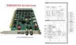
 - TMS320C5X ArchitectureTMS320C5X Architecture:The TMS320 DSP family consists of two types of single-chip DSPs: 16-bit fixed-point and 32-bit floating-point. These DSPs possess … Read more
- Advantages of Digital Signal ProcessingAdvantages of Digital Signal Processing: Advantages of DSP are Ease of Processing, Thermal Drift and Reliability, Repeatability, Immunity to Noise, … Read more
- [PDF] AE Agro Industries Corporation syllabus|595/2024 syllabus Kerala PSCAE Agro Industries Corporation syllabus: 595/2024 syllabus Kerala PSC: DETAILED SYLLABUS FOR THE POST OF ASSISTANT ENGINEER- THE KERALA AGRO … Read more
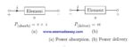
- Tellengen’s Theorem & ExampleTellengen’s Theorem: What is Tellengen’s theorem? Tellengen’s Theorem In any arbitrary network, the algebraic sum of the powers in all … Read more