Measurement of high resistance can be done by the methods such as Direct defelection method, Loss of charge method, Megaohm bridge, and megger method.
Measurement of high resistance
The methods that can be adopted for measuring resistances of the order of 0.1 MΩ and higher are:
- Direct deflection method
- Loss of charge method
- Megohm bridge
- Megger method
These are discussed as follows.
Direct Deflection Method
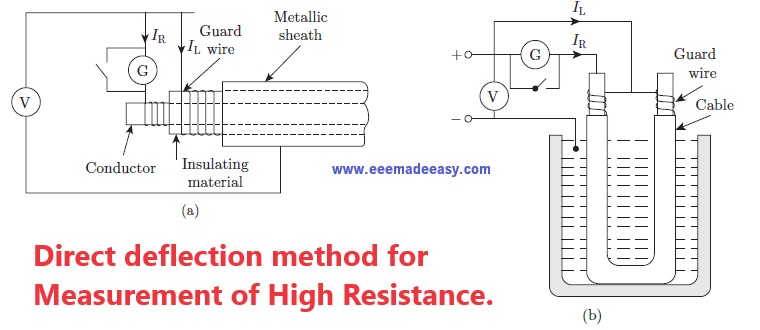
Figure (a) shows an arrangement for measurement of high resistance in cables having metallic sheath by direct deflection method.
The leakage current IL is carried by guard wire wound on the insulation and therefore does not flow through the galvanometer as shown.
Figure (b) shows the arrangement for measurement of high resistance in cables without metal sheaths.
The ends of the cable are immersed in water in a tank. The water and the tank then form the return path of the current.
The insulation resistance of the cable is, R = V/R
Loss of Charge Method
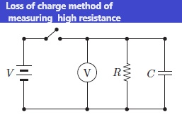
Figure shows the circuit for loss of charge method of measuring high resistances.
In this method, the unknown resistance is connected in parallel with capacitor and electrostatic voltmeter.
The capacitor is charged initially to a voltage V and then allowed to discharge through the resistance R. The voltmeter reading is v.
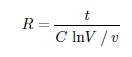
The terminal voltage during discharge is given by,
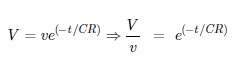
The insulation resistance is thus,
Megohm Bridge
Figure shows the circuit for the Megohm bridge.
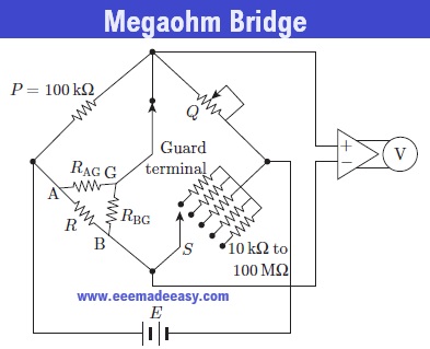
The circuit is completely self-contained and includes inbuilt power supplies, amplifiers, bridge members, and an indicating instrument. It has range from 0.1 MΩ to 106 MΩ.
The accuracy is usually within 3% to possible 10% above 10000 MΩ. Sensitivity of balancing at a high resistance is obtained by usage of adjustable high voltage supplies of 500 V to 1000 V.
The use of a sensitive null indicating arrangement such as a high gain amplifier with an electronic voltmeter or a cathode ray oscilloscope can also be used for the purpose.
Megger Method
Figure shows Megger arrangement for measuring high resistances. The current coil is the same as that in PMMC instrument.
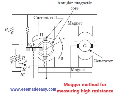
V1 and V2 are the two voltage coils and V1 encloses the annular magnetic core.
The voltage coil V1 is in weak magnetic field when the pointer is at infinity and so this coil exerts lesser torque.
The torque exerted by V1 increases as it moves into a stronger field.
This torque becomes maximum when it is under the pole face of the magnet and under this condition the pointer will be at zero of the resistance scale.
In order to modify the torque in the voltage circuit, another coil V2 is placed in the circuit.
This coil is located in such a way that it can move from infinity to zero. Coils V1 and V2 combined function like a spring of variable stiffness, such that.
It is very stiff near zero when the current in the current coil is very small due to the presence of unknown resistance Rx which is very large.
As a consequence, the low resistance portion of the scale is compressed and high resistance part of the scale opens up.
The voltage range for measurement using a Megger circuit can be controlled by varying the series resistance R (to R′or R′′) connected with the current coil.
The test voltages can be varied as 500, 1000 or 2500 V and can be supplied using generator G.
- [PDF]Electrical Measurements Measuring Instruments Study Notes PDF|EMMI Notes EEE Made Easy
- MCQ on Electrical Instruments
- Types of Errors in Instruments| Instrument Errors
- MCQ’s on Electrical Measuring Instruments|Instruments Objective Questions
- Electrical measuring instruments|Types of Measuring Instruments
- Static characteristics of instruments
- Types of measuring instruments- www.eeemadeeasy.com
- Moving Iron Instruments
- Instruments- Basics
- PMMC Instruments
- Types of instruments
- Essentials of Indicating instruments
- MCQ’s on Galvanometer|Galavnometer Questions & Answers
- MCQs on potentiometer|potentiometer Questions and answers
- TOD Meter or Time of Day Meter
- Light meters or illumination meter|Lux meter
- VU and decibel meters
- Multimeter- Principle and operation
- Digital readout meters-principle and operation
- Watt-hour meters- principle and operation
- Wattmeter -principle and working
- FET and vacuum-tube voltmeters
- Ohmmeter- basic principle and working
- Ammeters|Current Measurement
- Voltmeter- Principle and operation
- The household energy meter is
- Q Meter
- Thermistor| What is a Thermistor
- RTD vs Thermistor|Comparison between RTD and Thermistor
Latest Posts in EEE Made Easy
- [New] AE KWA Kerala PSC 2026AE KWA Kerala PSC 2026: DETAILED SYLLABUS FOR SELECTION TO THE POST OF ASSISTANT ENGINEER IN KERALA WATER AUTHOERITY AE … Read more
- [New] Electricity Worker KSEB Syllabus 2026|021/2026 Syllabus Kerala PSCElectricity Worker KSEB Syllabus 2026- 021/2026 Syllabus Kerala PSC: DETAILED SYLLABUS FOR THE POST OF ELECTRICITY WORKER IN KERALASTATE ELECTRICITY … Read more
- [Latest]KWA Operator Syllabus 2026|734,735/2025 Kerala PSC syllabusKWA Operator Syllabus 2026 – 734,735/2025 Kerala PSC syllabus: KERALA PUBLIC SERVICE COMMISSIONDETAILED SYLLABUS FOR THE POST OF OPERATOR (DIRECT) … Read more
- [New]Inspector of Legal Metrology Syllabus|613/2025 Kerala PSC SyllabusInspector of Legal Metrology Syllabus– 613/2025 Kerala PSC Syllabus: DETAILED SYLLABUS FOR THE POST OF INSPECTOR OF LEGAL METROLOGY IN … Read more
- [PDF]IE Rules|Indian Electricity Rules 1956
 IE Rules:The Indian Electricity Rules 1956 was made under section 37 of the Indian Electricity Act, 1910 and redefined after … Read more
 - [Latest]Syllabus Sub Engineer LSGD Electricity Wing Thrissur Corporation| 770/2025 Syllabus Kerala PSCSyllabus Sub Engineer LSGD Electricity Wing Thrissur Corporation: DETAILED SYLLABUS FOR THE POST OF SUB ENGINEER IN LSGD(ELECTRICITY WING OF … Read more
- Compensating WindingsCompensating Windings: Compensating Windings are used for large direct current machines which are subjected to large fluctuations in load i.e. … Read more

Join EEE Made Easy Whatsapp Channel
Latest Posts in EEE Made Easy
- [New] AE KWA Kerala PSC 2026AE KWA Kerala PSC 2026: DETAILED SYLLABUS FOR SELECTION TO THE POST OF ASSISTANT ENGINEER IN KERALA WATER AUTHOERITY AE … Read more
- [New] Electricity Worker KSEB Syllabus 2026|021/2026 Syllabus Kerala PSCElectricity Worker KSEB Syllabus 2026- 021/2026 Syllabus Kerala PSC: DETAILED SYLLABUS FOR THE POST OF ELECTRICITY WORKER IN KERALASTATE ELECTRICITY … Read more
- [Latest]KWA Operator Syllabus 2026|734,735/2025 Kerala PSC syllabusKWA Operator Syllabus 2026 – 734,735/2025 Kerala PSC syllabus: KERALA PUBLIC SERVICE COMMISSIONDETAILED SYLLABUS FOR THE POST OF OPERATOR (DIRECT) … Read more
- [New]Inspector of Legal Metrology Syllabus|613/2025 Kerala PSC SyllabusInspector of Legal Metrology Syllabus– 613/2025 Kerala PSC Syllabus: DETAILED SYLLABUS FOR THE POST OF INSPECTOR OF LEGAL METROLOGY IN … Read more
- [PDF]IE Rules|Indian Electricity Rules 1956IE Rules:The Indian Electricity Rules 1956 was made under section 37 of the Indian Electricity Act, 1910 and redefined after … Read more
- [Latest]Syllabus Sub Engineer LSGD Electricity Wing Thrissur Corporation| 770/2025 Syllabus Kerala PSCSyllabus Sub Engineer LSGD Electricity Wing Thrissur Corporation: DETAILED SYLLABUS FOR THE POST OF SUB ENGINEER IN LSGD(ELECTRICITY WING OF … Read more
- Compensating WindingsCompensating Windings: Compensating Windings are used for large direct current machines which are subjected to large fluctuations in load i.e. … Read more