Circuit Breaker types: According to different criteria, there are different types of circuit breakers.
What is a Circuit Breaker?
A circuit breaker is an electrical safety device designed to protect an electrical circuit from damage caused by overcurrent.
circuit breaker‘s basic function is to interrupt current flow to protect equipment and to prevent the risk of fire.
Unlike a fuse, which operates once and then must be replaced, a circuit breaker can be reset (either manually or automatically) to resume normal operation.
Types of circuit breaker
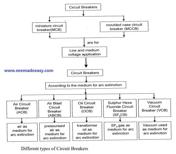
According to their arc quenching media, the circuit breaker can be divided as
- Oil circuit breaker
- Air circuit breaker
- SF6 circuit breaker.
- Vacuum circuit breaker.
According to their services, the circuit breaker can be divided as
- Outdoor circuit breaker
- Indoor breaker.
According to the operating mechanism of circuit breaker they can be divided as-
- Spring-operated circuit breaker.
- Pneumatic circuit breaker.
- Hydraulic circuit breaker.
According to the voltage level of installation types of circuit breaker are referred as-
- High voltage circuit breaker
- Medium voltage circuit breaker
- Low voltage circuit breaker.
Air Circuit Breaker
Air Circuit Breakers are of two types;
- Air Blast Circuit Breaker
- Air Breake Circuit Breaker
Air Blast Circuit Breaker
Air Blast Circuit Breaker, is a kind of circuit breaker which operates in air at atmospheric pressure.
After the development of the oil circuit breaker, the medium voltage air circuit breaker (ACB) is
replaced completely by oil circuit breakers in different countries.
Working Principle of Air Circuit Breaker
The working principle of Air Circuit Breaker is rather different from those in any other types of circuit breaker.
The main aim of all kinds of circuit breakers is to prevent the re establishment of arcing
after current zero by creating a situation where in the contact gap will withstand the system
recovery voltage.
The air circuit breaker does the same but in a different manner. For interrupting arc it creates an arc voltage in excess of the supply voltage.
Arc voltage is defined as the minimum voltage required to maintain the arc.
This circuit breaker increases the arc voltage by three different ways,
It may increase the arc voltage by cooling the arc plasma.
As the temperature of arc plasma is decreased, the mobility of the particle in arc plasma is reduced, hence more voltage gradient is required to maintain the arc.
It may increase the arc voltage by lengthening the arc path.
As the length of arc path is increased, the resistance of the path is increased, and hence to maintain the same arc current more voltage is required to be applied across the arc path. That means arc voltage is increased.
Splitting up the arc into a number of series arcs also increases the arc voltage.
Types of ACB
There are mainly two types of ACB are available.
- Plain air circuit breaker.
- Air blast Circuit Breaker.
Operation of ACB
The first objective is usually achieved by forcing the arc into contact with as large an area
as possible of insulating material.
Every air circuit breaker is fitted with a chamber surrounding the contact.
This chamber is called ͚arc chute͛.
The arc is driven into it. If inside of the arc chute is suitably shaped, and if the arc can be made conform to the shape, the arc chute wall will help to achieve cooling.
This type of arc chute should be made from some kind of refractory material. High temperature plastics reinforced with glass fiber and ceramics are preferable materials for making arc chute.
The second objective that is lengthening the arc path, is achieved concurrently with fist
objective. If the inner walls of the arc chute is shaped in such a way that the arc is not only
forced into close proximity with it but also driven into a serpentine channel projected on
the arc chute wall. The lengthening of the arc path increases the arc resistance.
The third technique is achieved by using metal arc slitter inside the arc chute. The main arc chute is divided into numbers of small compartments by using metallic separation plates.
These metallic separation plates are actually the arc splitters and each of the small
compartments behaves as individual mini arc chute.
In this system the initial arc is split into a number of series arcs, each of which will have its mini arc chute. So each of the split arcs has its won cooling and lengthening effect due to its mini arc chute and hence individual split arc voltage becomes high.
These collectively, make the overall arc voltage, much higher than the system voltage.
AIR BREAK CIRCUIT BREAKER (ACB)
The air circuit breaker, operated within the voltage level 1 KV, does not require any arc control
device.
Mainly for heavy fault current on low voltages (low voltage level above 1 KV) ABCs with
appropriate arc control device, are good choice.
These breakers normally have two pairs of contacts. The main pair of contacts carries the current at normal load and these contacts are made of copper.
The additional pair is the arcing contact and is made of carbon.
When circuit breaker is being opened, the main contacts open first and during opening of main contacts the arcing contacts are still in touch with each other.
As the current gets, a parallel low resistive path through the arcing contact during opening of main contacts, there will not be any arcing in the main contact.
The arcing is only initiated when finally the arcing contacts are separated. Each
of the arc contacts is fitted with an arc runner which helps, the arc discharge to move upward due to both thermal and electromagnetic effects as shown in the figure.
As the arc is driven upward it enters in the arc chute, consisting of splitters. The arc in chute will become colder, lengthen and split hence arc voltage becomes much larger than system voltage at the time of operation of air circuit breaker, and therefore the arc is quenched finally during the current zero.
Although this type of circuit breakers have become obsolete for medium voltage application, but they are still preferable choice for high current rating in low voltage application.
Air Blast Circuit Breaker
These types of air circuit breaker were used for the system voltage of 245 KV, 420 KV and even more, especially where faster breaker operation was required.
Air blast circuit breaker has some specific advantages over oil circuit breaker which are listed as follows,
- There is no chance of fire hazard caused by oil.
- The breaking speed of circuit breaker is much higher during operation of air blast circuit
breaker. - Arc quenching is much faster during operation of air blast circuit breaker.
- The duration of arc is same for all values of small as well as high currents interruptions.
- As the duration of arc is smaller, so lesser amount of heat realized from arc to current
carrying contacts hence the service life of the contacts becomes longer
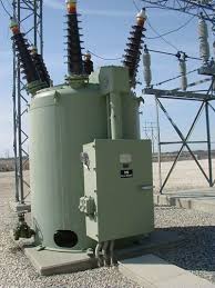
Minimum Oil Circuit Breaker or MOCB
These types of circuit breakers utilize oil as the interrupting media. However, unlike bulk oil
circuit breaker, a minimum oil circuit breaker places the interrupting unit in insulating
chamber at live potential.
The insulating oil is available only in interrupting chamber.
The feature of designing MOCB is to reduce requirement of oil, and hence these breaker are
called minimum oil circuit breaker.
As the volume of the oil in bulk oil circuit breaker is huge, the chances of fire hazard in bulk oil
system are more.
For avoiding unwanted fire hazard in the system, one important development in the design of oil circuit breaker has been introduced where use of oil in the circuit breaker is much less than that of bulk oil circuit breaker.
It has been decided that the oil in the circuit breaker should be used only as arc quenching media not as an insulating media.
Then the concept of minimum oil circuit breaker comes. In this type of circuit breaker the arc interrupting device is enclosed in a tank of insulating material which as a whole is at live potential of system.
This chamber is called arcing chamber or interrupting pot. The gas pressure developed in the arcing chamber depends upon the current to be interrupted.
Higher the current to be interrupted causes larger the gas pressure developed inside the chamber, hence better the arc quenching.
But this put a limit on the design of the arc chamber for mechanical stresses.
With use of better insulating materials for the arcing chambers such as glass fiber, reinforced synthetic resin etc, the minimum oil circuit breaker are able to meet easily the increased fault levels of the system.
Working Principle or Arc Quenching in Minimum Oil Circuit Breaker
Working Principle of minimum oil circuit breaker or arc quenching in minimum oil circuit
breaker is described below.
In a minimum oil circuit breaker, the arc drawn across the current carrying contacts is contained inside the arcing chamber Hence the hydrogen bubble formed by the vaporized oil is trapped inside the chamber.
As the contacts continue to move, after its certain travel an exit vent becomes available for exhausting the trapped hydrogen gas.
There are two different types of arcing chamber is available in terms of venting are provided in the arcing chambers.
One is axial venting and other is radial venting.
In axial venting, gases (mostly Hydrogen), produced due to vaporization of oil and
decomposition of oil during arc, will sweep the arc in axial or longitudinal direction.
Let‟s have a look on working principle Minimum Oil Circuit Breaker with axial venting arc
chamber.
The moving contact has just been separated and arc is initiated in MOCB.
The ionized gas around the arc sweep away through upper vent and cold oil enters into the arcing chamber through the lower vent in axial direction as soon as the moving contact tip crosses the lower vent opening and final arc quenching in minimum oil circuit breaker occurs the cold oil occupies the gap between fixed contact and moving contact and the minimum oil circuit breaker finally comes into open position.
Whereas in case of radial venting or cross blast, the gases (mostly Hydrogen) sweep the arc in radial or transverse direction.
The axial venting generates high gas pressure and hence has high dielectric strength, so it is mainly used for interrupting low current at high voltage.
On the other hand radial venting produces relatively low gas pressure and hence low dielectric strength so it can be used for low voltage and high current interruption.
Many times the combination of both is used in minimum oil circuit breaker so that the chamber is equally efficient to interrupt low current as well as high current.
These types of circuit breaker are available up to 8000 MVA at 245 KV.
Vacuum Circuit Breaker or VCB
A vacuum circuit breaker is such kind of circuit breaker where the arc quenching takes place in
vacuum.
The technology is suitable for mainly medium voltage application.
For higher voltage vacuum technology has been developed but not commercially viable.
The operation of opening and closing of current carrying contacts and associated arc interruption take place in a vacuum chamber in the breaker which is called vacuum interrupter.
The vacuum interrupter consists of a steel arc chamber in the centre symmetrically arranged ceramic insulators.
The vacuum pressure inside a vacuum interrupter is normally maintained at 10 – 6
bar.
The material used for current carrying contacts plays an important role in the performance of
the vacuum circuit breaker.
CuCr is the most ideal material to make VCB contacts. Vacuum interrupter technology was first introduced in the year of 1960.
But still it is a developing technology.
As time goes on, the size of the vacuum interrupter is being reducing from its early
1960‟s size due to different technical developments in this field of engineering.
The contact geometry is also improving with time, from butt contact of early days it gradually changes to spiral shape, cup shape and axial magnetic field contact.
The vacuum circuit breaker is today recognized as most reliable current interruption technology for medium voltage switchgear.
It requires minimum maintenance compared to other circuit breaker technologies.
Advantages of Vacuum Circuit Breaker or VCB
Service life of vacuum circuit breaker is much longer than other types of circuit breakers.
There is no chance of fire hazard as oil circuit breaker.
It is much environment friendly than SF6 Circuit breaker.
Beside of that contraction of VCB is much user friendly.
Replacement of vacuum interrupter (VI) is much convenient.
Operation of Vacuum Circuit Breaker
The main aim of any circuit breaker is to quench arc during current zero crossing, by establishing high dielectric strength in between the contacts so that reestablishment of arc after current zero becomes impossible.
The dielectric strength of vacuum is eight times greater than that of air and four times greater than that of SF6 gas.
This high dielectric strength makes it possible to quench a vacuum arc within very small contact gap.
For short contact gap, low contact mass and no compression of medium the drive energy required in vacuum circuit breaker is minimum.
When two face to face contact areas are just being separated to each other, they do not be separated instantly, contact area on the contact face is being reduced and ultimately comes to a point and then they are finally de-touched.
Although this happens in a fraction of micro second but it is the fact.
At this instant of de-touching of contacts in a vacuum, the current through the contacts
concentrated on that last contact point on the contact surface and makes a hot spot.
As it is vacuum, the metal on the contact surface is easily vaporized due to that hot spot and create a conducting media for arc path.
Then the arc will be initiated and continued until the next current zero.
At current zero this vacuum arc is extinguished and the conducting metal vapor is re-condensed on the contact surface.
At this point, the contacts are already separated hence there is no question of re-vaporization of contact surface, for next cycle of current.
That means, the arc cannot be reestablished again. In this way vacuum circuit breaker prevents the reestablishment of arc by producing high dielectric strength in the contact gap after current zero.
There are two types of arc shapes.
For interrupting current up to 10 kA, the arc remains diffused and the form of vapor discharge and cover the entire contact surface.
Above 10 kA the diffused arc is constricted considerably by its own magnetic field and it contracts.
The phenomenon gives rise over heating of contact at its center.
In order to prevent this, the design of the contacts should be such that the arc does not remain stationary but keeps travelling by its own magnetic field.
Specially designed contact shape of vacuum circuit breaker make the constricted stationary arc travel along the surface of the contacts, thereby causing minimum and uniform contact erosion.
SF6 Circuit Breaker
A circuit breaker in which the current carrying contacts operate in sulphur hexafluoride
or SF6 gas is known as an SF6 circuit breaker.
SF6 has excellent insulating property.
SF6 has high electro-negativity.
That means it has high affinity of absorbing free electron.
Whenever a free electron collides with the SF6 gas molecule, it is absorbed by that gas molecule and forms a negative ion.
The attachment of electron with SF6 gas molecules may occur in two different
ways,
Read: Relay and Circuit Breakers MCQ Questions|EEE Made Easy
These negative ions obviously much heavier than a free electron and therefore over all
mobility of the charged particle in the SF6 gas is much less as compared other common gases.
We know that mobility of charged particle is majorly responsible for conducting current through
a gas Hence, for heavier and less mobile charged particles in SF6 gas, it acquires very high
dielectric strength.
Not only the gas has a good dielectric strength but also it has the unique property of fast recombination after the source energizing the spark is removed.
The gas has also very good heat transfer property.
Due to its low gaseous viscosity (because of less molecular mobility) SF6 gas can efficiently transfer heat by convection.
So due to its high dielectric strength and high cooling effect SF6gas is approximately 100 times more effective arc quenching media than air.
Due to these unique properties of this gas SF6 circuit breaker is used in complete range of mediumvoltage and high voltage electrical power system.
These circuit breakers are available for the voltage ranges from 33KV to 800KV and even more.
Disadvantages of SF6 CB
The SF6 gas is identified as a greenhouse gas, safety regulation are being introduced in
many countries in order to prevent its release into atmosphere.
Puffer type design of SF6 CB needs a high mechanical energy which is almost five times greater than that of oil circuit breaker.
Types of SF6 Circuit Breaker
There are mainly three types of SF6 CB depending upon the voltage level of application1.
- Single interrupter SF6 CB applied for up to 245 KV(220 KV) system.
- Two interrupter SF6 CB applied for up to 420 KV(400 KV) system.
- Four interrupter SF6 CB applied for up to 800 KV(715 KV) system.
Working of SF6 Circuit Breaker
The working of SF6 CB of first generation was quite simple it is some extent similar to
air blast circuit breaker. Here SF6 gas was compressed and stored in a high pressure reservoir.
During operation of SF6 circuit breaker this highly compressed gas is released through the arc
in breaker and collected to relatively low pressure reservoir and then it pumped back to the high pressure reservoir for re utilize.
The working of SF6 circuit breaker is little bit different in modern time. Innovation of
puffer type design makes operation of SF6 CB much easier.
In buffer type design, the arc energy is utilized to develop pressure in the arcing chamber for arc quenching.
Here the breaker is filled with SF6 gas at rated pressure.
There are two fixed contact fitted with a specific contact gap.
A sliding cylinder bridges these to fixed contacts.
The cylinder can axially slide upward and downward along the contacts.
There is one stationary piston inside the cylinder which is fixed with other stationary parts of the SF6 circuit breaker, in such a way that it cannot change its position during the movement of the cylinder.
As the piston is fixed and cylinder is movable or sliding, the internal volume of the cylinder changes when the cylinder slides.
During opening of the breaker the cylinder moves downwards against position of the
fixed piston hence the volume inside the cylinder is reduced which produces compressed SF6gas inside the cylinder.
The cylinder has numbers of side vents which were blocked by upper fixed contact body during closed position.
As the cylinder move further downwards, these vent openings cross the upper fixed contact, and become unblocked and then compressed SF6 gas inside the cylinder will come out through this vents in high speed towards the arc and passes through the axial hole of the both fixed contacts.
The arc is quenched during this flow of SF6 gas.
During closing of the circuit breaker, the sliding cylinder moves upwards and as the
position of piston remains at fixed height, the volume of the cylinder increases which introduces
low pressure inside the cylinder compared to the surrounding.
Due to this pressure difference SF6 gas from surrounding will try to enter in the cylinder. The higher pressure gas will come through the axial hole of both fixed contact and enters into cylinder via vent and during this flow; the gas will quench the arc.
D.C circuit breakers
Miniature circuit breakers available for use in direct current Nowadays we use more commonly miniature circuit breaker or MCB in low voltage electrical network instead of fuse.
The MCB has some advantages compared to fuse.
It automatically switches off the electrical circuit during abnormal condition of the network
means in over load condition as well as faulty condition.
The fuse does not sense but miniature circuit breaker does it in more reliable way.
MCB is much more sensitive to over current than fuse.
Another advantage is, as the switch operating knob comes at its off position during tripping,
the faulty zone of the electrical circuit can easily be identified.
But in case of fuse, fuse wire should be checked by opening fuse grip or cutout from fuse base, for confirming the blow of fuse wire.
Quick restoration of supply cannot be possible in case of fuse as because fuses have to be
replaced for restoring the supply.
But in the case of MCB, quick restoration is possible by just switching on operation.
MCB advantages over Fuse
Handling MCB is more electrically safe than fuse.
Because of too many advantages of MCB over fuse units, in modern low voltage electrical
network, miniature circuit breaker is mostly used instead of backdated fuse unit.
Only one disadvantage of MCB over fuse is that this system is more costly than fuse unit system.
Working Principle Miniature Circuit Breaker
There are two arrangement of operation of miniature circuit breaker.
One due to thermal effect of over current and other due to electromagnetic effect of over current.
The thermal operation of miniature circuit breaker is achieved with a bimetallic strip whenever
continuous over current flows through MCB, the bimetallic strip is heated and deflects by
bending.
This deflection of bimetallic strip releases mechanical latch.
As this mechanical latch is attached with operating mechanism, it causes to open the miniaturecircuit breaker contacts.
But during short circuit condition, sudden rising of current, causes electromechanical displacement of plunger associated with tripping coil or solenoid of MCB.
The plunger strikes the trip lever causing immediate release of latch mechanism consequently open the circuit breaker contacts.
This was a simple explanation of miniature circuit breaker working principle.
Miniature Circuit Breaker Construction
Miniature circuit breaker construction is very simple, robust and maintenance free.
Generally a MCB is not repaired or maintained, it just replaced by new one when required.
A miniature circuit breaker has normally three main constructional parts.
These are:
Frame of Miniature Circuit Breaker
The frame of miniature circuit breaker is a molded case. This is a rigid, strong, insulated
housing in which the other components are mounted.
Operating Mechanism of Miniature Circuit Breaker
The operating mechanism of miniature circuit breaker provides the means of manual
opening and closing operation of miniature circuit breaker.
It has three-positions “ON,” “OFF,”and “TRIPPED”.
The external switching latch can be in the “TRIPPED” position, if the MCB is tripped due to over-current.
When manually switch off the MCB, the switching latch will be in “OFF” position.
In close condition of MCB, the switch is positioned at “ON”.
By observing the positions of the switching latch one can determine the condition of MCB whether it is closed, tripped or manually switched off.
Trip Unit of Miniature Circuit Breaker
The trip unit is the main part, responsible for proper working of miniature circuit
breaker.
Two main types of trip mechanism are provided in MCB.
A bimetal provides protection against over load current and an electromagnet provides protection against shortcircuit current.
Operation of Miniature Circuit Breaker
There are three mechanisms provided in a single miniature circuit breaker to make it
switched off.
If we carefully observe the picture beside, we will find there are mainly one bimetallic strip, one trip coil and one hand operated on – off lever.
Electric current carrying path of a miniature circuit breaker shown in the picture is like follows.
First left hand side power terminal – then bimetallic strip – then current coil or trip coil – then moving contact – then fixed contact and – lastly right had side power terminal.
All are arranged in series.
If circuit is overloaded for long time, the bi – metallic strip becomes over heated and
deformed.
This deformation of bi metallic strip causes, displacement of latch point.
The moving
contact of the MCB is so arranged by means of spring pressure, with this latch point, that a little
displacement of latch causes, release of spring and makes the moving contact to move for
opening the MCB.
The current coil or trip coil is placed such a manner, that during short circuit fault the mmf of that coil causes its plunger to hit the same latch point and make the latch to be
displaced.
Hence the MCB will open in same manner.
Again when operating lever of the miniature circuit breaker is operated by hand, that means when we make the MCB at off position manually, the same latch point is displaced as a result moving contact separated from fixed contact in same manner.
So, whatever may be the operating mechanism, that means, may be due to deformation of bi – metallic strip, due to increased mmf of trip coil or may due to manual operation, actually the same latch point is displaced and same deformed spring is released, which ultimately responsible for movement of the moving contact.
When the the moving contact separated from fixed contact, there may be a high chance of arc.
Relay and Circuit Breakers MCQ Questions|EEE Made Easy
More on Circuit Breakers
- Relay and Circuit Breakers MCQ Questions|EEE Made Easy
- How to open a circuit breaker
- Difference between Isolator and Circuit breaker|Isolator Vs Circuit breaker
- Types of circuit breaker| Circuit Breaker Types
- Difference between Fuse and Circuit breaker|Fuse vs Circuit Breaker
- Fuse|Electrical Fuse
Latest Posts in EEE Made Easy
- Energy Efficient Lamps|CFL, LED lamps
 Energy Efficient Lamps: CFL (Compact Fluorescent lamp ) and LED (light emitting diodes) lamp are Energy Efficient Lamps. Energy Efficient … Read more
 - [New] AE KWA Kerala PSC 2026AE KWA Kerala PSC 2026: DETAILED SYLLABUS FOR SELECTION TO THE POST OF ASSISTANT ENGINEER IN KERALA WATER AUTHOERITY AE … Read more
- [New] Electricity Worker KSEB Syllabus 2026|021/2026 Syllabus Kerala PSCElectricity Worker KSEB Syllabus 2026- 021/2026 Syllabus Kerala PSC: DETAILED SYLLABUS FOR THE POST OF ELECTRICITY WORKER IN KERALASTATE ELECTRICITY … Read more
- [Latest]KWA Operator Syllabus 2026|734,735/2025 Kerala PSC syllabusKWA Operator Syllabus 2026 – 734,735/2025 Kerala PSC syllabus: KERALA PUBLIC SERVICE COMMISSIONDETAILED SYLLABUS FOR THE POST OF OPERATOR (DIRECT) … Read more
- [New]Inspector of Legal Metrology Syllabus|613/2025 Kerala PSC SyllabusInspector of Legal Metrology Syllabus– 613/2025 Kerala PSC Syllabus: DETAILED SYLLABUS FOR THE POST OF INSPECTOR OF LEGAL METROLOGY IN … Read more
- [PDF]IE Rules|Indian Electricity Rules 1956IE Rules:The Indian Electricity Rules 1956 was made under section 37 of the Indian Electricity Act, 1910 and redefined after … Read more
- [Latest]Syllabus Sub Engineer LSGD Electricity Wing Thrissur Corporation| 770/2025 Syllabus Kerala PSCSyllabus Sub Engineer LSGD Electricity Wing Thrissur Corporation: DETAILED SYLLABUS FOR THE POST OF SUB ENGINEER IN LSGD(ELECTRICITY WING OF … Read more