Objective Questions and Answers on DC voltages and circuits
2.1 A voltage of 0.0025 V expressed in microvolts
is
• a 25 Micro Volts
• b 250 Micro Volts
• c 2.5Micro Volts
• d 2500 Micro Volts
2.2 A voltage of 800 mV expressed in volts is
• a 0.008 V
• b 0.08 V
• c 0.8 V
• d 8.0 V
2.3 A voltage of 0.36 mV expressed in microvolts is
• a 360 ìí
• b 36 ìí
• c 3.6 ìí
• d 3600 ìí
2.4 A voltage of 800 × 10 3 Micro Volts expressed in millivolts is
• a 80 mV
• b 800 mV
• c 8.0 mV
• d 8000 mV
2.5 A voltage of 0.25 kV expressed in volts is
• a 2.5 V
• b 25 V
• c 250 V
• d 2500 V
2.6 If 2.4 J are required to move 15 C from
point A to point  in a circuit, the potential
difference between the two points is
• a 0.12 V
• b 0.16 V
• c 6.25 V
• d 6.75 V
2.7 A current of 0.5 A is measured at a circuit point over a period of 2 min. The charge that has passed that point is
• a 1 0 C
• b 20 C
• c 40 C
• d 60 C
2.8 If the current at a circuit point is 0.25 A, the time for 7.5 C to flow is
• a 30 s
• b 35 s
• c 3.5 s
• d 2.5 s
2.9 If the parameters in Question 2.8 are 100 mA and 0.5 C, the time is
• a 0.5 s
• b 5.0 s
• c 50 s
• d 500 s
2.10 If there is a flow of 360 C in a resistor over a period of 30 min, the current is
• a 200 mA
• b 360 mA
• c 2 A
• d 20 A
2.11 If the parameters for Question 2.10 are 60
mC and 2 hours, the current is
• a 4.33 ìÁ
• ft 6.67 ìÁ
• c 7.33 ìÁ
• d 8.33 ìÁ
2.12 A current of 20 mA expressed in amps is
• a 0.002 A
• b 0.02 A
• c 0.2 A
• d 2.0 A
Best Books for KSEB AE Exam
- Assistant Engineer Electrical KSEB Books list
- Question Bank In Electrical Engineering (Fully Solve With Explanations)
- Kerala PSC OBJECTIVE ELECTRICAL ENGINEERING
- PSC PREVIOUS QUESTION AND ANSWERS IN ELECTRICAL / ELECTRONICS ENGINEERING
- Best Books for Assistant Professor in Electrical and Electronics Engineering|Best Books for Kerala PSC Assistant Professor Electrical Engineering
2.13 A current of 60 ì A expressed in milliamps
is
• a 600 mA
• H m A
• c 0.6 mA
• d 0.06 mA
2.14 A power of 0.05 MW expressed in kilowatts
is
• a 0.5 kW
• b 5 kW
• c 50 kW
• d 500 kW
2.15 A power of 12 mW is equivalent to
• a 12 × 10″ 3 W
• b 12 X 10^-6 W
• c 12 × 10^3 W
• d 12 × 10 ^ 6 W
2.16 The diagram shows a single resistor connected to a DC supply. The current / is
• a 2 A
• b 0.2 A
• c 0.5 A
• d 2 mA
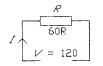
2.17 The input power in Question 2.16 is
• a 240 W
• b 30 W
• c 120 W
• d 2 W
2.18 If the resistor in Question 2.16 is changed to
24R, the input current is then
• a 20 ìÁ
• b 200 ìÁ
• c 20 mA
• d 5 A
2.19 The input power in Question 2.18 is
• a 12 W
• ft 20 W
• c 22 W
• d 600 W
2.20 The diagram shows two resistors connected
in parallel and driven by a DC supply. The
current / is
• a 0.2 A
• ft 2.4 A
• c 3.6 A
• d 4.0 A
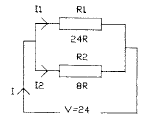
2.21 In Question 2.20 the value of current Ix is
• a 10 mA
• ft 100 mA
• c 1.0 A
• d 2.0 A
2.22 In Question 2.20 the value of current I2 is
• a 2.0 A
• ft 3.0 A
• c 200 mA
• d 300 mA
2.23 In Question 2.20 the input power is
• a 20 W
• b 46 W
• c 80 W
• d 96 W
2.24 In Question 2.20 the power dissipated in Rx is
• a 24 W
• b 48 W
• c 60 W
• d 80 W
2.25 In Question 2.20 the power dissipated in R2
is
• a 60 W
• * 72 W
• c 78 W
• d 82 W
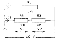
2.26 The diagram shows a series circuit. The
value of / is
• a 6 A
• b 4 A
• c 2 A
d 1 A
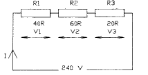
2.27 The value of V3 in Question 2.26 is
• a 40 V
• b 60 V
• c 2 0 V
• d 10 V
2.28 The value of the input power in Question
2.26 is
• a 70 W
• b 140 W
• c 200 W
• d 480 W
2.29 The value of the power consumed in Rx in
Question 2.26 is
• a 100 W
U b 160 W
• c 180 W
• d 200 W
2.30 The value of the power consumed by R2 in Question 2.26 is
• a 240 W
• b 260 W
• c 280 W
• d 300 W
2.31 The diagram shows a parallel circuit. The value of current / is
• a 1.5 A
• b 2.0 A
• c 2.5 A
• d 3.0 A
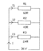
2.32 The value of the current I2 in Question 2.31 is
• a 600 mA
• b 750 mA
• c 900 mA
• d 920 mA
2.33 The value of the current I3 in Question 2.31 is
• a 1.5 A
• b 1.75 A
• c 2.25 A
• d 2.5 A
2.34 The value of the power consumed by Rx in Question 2.31 is
• a 20.5 W
• b 21.6 W
• c 22.4 W
• d 24.2 W
2.35 The value of the power consumed by R2 in Question 2.31 is
• a 20.5 W
• b 30.2 W
• c 32.4 W
• d 33.6 W
2.36 Four resistors having values of 150R, 250R, IkO and lk5 are connected in parallel. The
combined resistance is
• a 33.33R
• b 47.67R
• c 81.08R
• d 120.33R
2.37 The combined value of four resistors connected in parallel is 40R. If three of the
resistors have values of 80R, 160R and 200R, the value of the fourth is
• a 360R
• b 480R
• c 640R
• d 800R
2.38 A meter gives a full scale deflection with a
current of 0.5 mA, and it has a resistance of
0.5 Ù. The series resistance needed for it to
read up to 2 V is
• a 3999R5
• b 4000R
• c 5000R5
• d 5500R
2.39 If the meter in Question 2.38 is required to
read up to 10 V, the series resistance would
need to be
• a 1999R
• b 1999R5
• c 19999R
• d 19999R5
Download & Install EEE Made Easy App
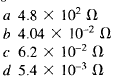
2.40 An ammeter gives full-scale deflection with a current of 20 mA, and it has a coil resistance of 4 Ù. The value of the shunt resistance required to enable it to read up to 2 A is
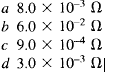
2.41 If the meter in Question 2.40 is required to read up to 10 A, the shunt resistance
required is
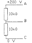
2.42 A voltmeter having a resistance of 20k0 is used to measure the voltage between points
A and  in the diagram shown. The meter will indicate a voltage of
• a 20 V
• b 60 V
• c 8 0 V
• d 100 V
2.43 If the voltmeter in Question 2.42 has a resistance of lOOkO, the voltage indicated is
• a 75.3 V
• b 89.2 V
• c 90.43 V
• d 95.23 V
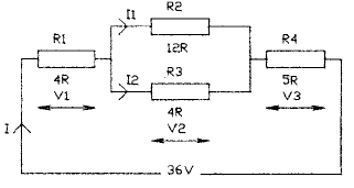
2.44 The diagram shows a series-parallel circuit.
The value of / is
• a 1.5 A
• ft 2.4 A
• c 2.8 A
• d 3.0 A
2.45 In Question 2.44 the value of V2 is
• a 9 V
• ft 10 V
• c 12 V
• d 22 V
2.46 In Question 2.44 the value of V3 is
• a 6 V
• ft 10 V
• c 12 V
• J 15 V
2.47 In Question 2.44 the value of Ix is
• a 0.5 A
• ft 0.75 A
• c 1.0 A
• d 1.25 A
2.48 In Question 2.44 the value of I2 is
• a 1.75 A
• ft 2.0 A
• c 2.25 A
• d 2.5 A
2.49 In Question 2.44 the power consumed by R2
is
• a 2.4 W
• ft 6.75 W
• c 8.2 W
• d 9.5 W
2.50 In Question 2.44 the power consumed by R3 is
U.a 20.25 W
• ft 24.25 W
• c 24.75 W
• d 30.25 W
2.51 In Question 2.44 the power consumed by R4 is
• a 25 W
• ft 35 W
• c 45 W
• J 55 W
Download & Install Job Search India App for daily Job Updates
2.52 The diagram shows a Wheatstone bridge
which is in balance. The value of the
unknown resistor R4 is
• a 15k0
• ft 22k0
• c 33kO
• d 47k0
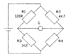
2.53 If the bridge in Question 2.52 is balanced,
with R2 changed to 680R, the value of R4
is
• a 4k7
• ft 6k8
• c 5k6
• d 3k3
2.54 Six resistors are connected in parallel. Three
have values of lk44 and three have values
of 480R. The combined resistance is
• a 100R
• ft 120R
• c 200R
• d 240R
2.55 Five lk5 resistors are connected in parallel.
It is a requirement to add a sixth resistor in
parallel with the network to give a combined
resistance of 21 OR. The value of the
additional resistor is
• a 550R
• ft 650R
• c 700R
• d 800R
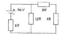
2.56 The diagram shows a series-parallel circuit.
The value of current / is
• a 6.67 A
• b 8.33 A
• c 10.67 A
• d 13.33 A
2.57 The value of current I2 in Question 2.56 is
• a 3.33 A
• * 3.93 A
• c 4.33 A
• d 4.67 A
2.58 The value of the voltage Vx in Question 2.56
is
• a 50 V
• b 70 V
• c 9 0 V
• d 100 V
2.59 The value of the power dissipated in Rx in 2.65 is
• a 900 W
• b1000 W
• c 1100 W
• d 1200 W
2.60 The value of the power dissipated in R3 in
Question 2.56 is
• a 50.33 W
• b 66.67 W
• c 69.33 W
• d 72.67 W
2.61 The diagram shows a series-parallel circuit.
The value of R4 is
• a 16R
• b 24R
• c 36R
• d 48R
2.62 The voltage across resistor Rx in Question
2.61 is
• a 18 V
• b 16 V
• c 2 0 V
• d 12 V
2.63 The power consumed by R2 in Question
2.61 is
• a 12 W
• ft 15 W
• c 28 W
• d 36 W
2.64 The power consumed by R4 in Question
2.61 is
• a 20 W
• ft 144 W
• c 240 W
2.65 If R4 in Question 2.61 is changed so that the
input current is 1.714 A, the value of R4 is
• a 24R
• ft 48R
• c 64R
• d 96R
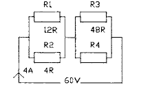
2.66 The diagram shows a four-resistor network.
The value of the current flowing in the 6R
resistor is
• a 2 A
• b 4 A
• c 6 A
• d 8 A
2.67 In Question 2.66 the current flowing in the
12R resistor is
• a 2 A
• b 3 A
• c 4 A
• d 5 A
2.68 In Question 2.66 the current flowing in the
8R resistor is
• a 4 A
• b 6 A
• c 8 A
• J 10 A
2.69 If the battery voltage in Question 2.66 is
increased to 108 V, the current flowing in
the 6R resistor becomes
• a 8.5 A
• b 9.0 A
• c 10.0 A
• d 10.5 A
2.70 If the battery voltage in Question 2.66 is
increased to 108 V, the current flowing in
the 4R resistor becomes
• a 6.5 A
• b 3.5 A
• c 7.5 A
• d 4.5 A
2.71 The diagram shows a network containing
two batteries. The current flowing through
the 5R resistor is
• a 0.623 A
• b 0.658 A
• c 0.706 A
• d 0.714 A
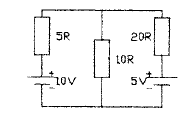
2.72 The current flowing through the 10R resistor
in Question 2.71 is
• a 0.643 A
• b 0.683 A
• c 0.723 A
• d 0.753 A
2.73 The current flowing through the 20R resistor
in Question 2.71 is
• a 0.06 A
• b 0.064 A
• c 0.069 A
• d 0.071 A
2.74 The voltage between the top and bottom
rails of the network in Question 2.71 is
• a 2.62 V
• b 4.53 V
• c 6.43 V
• d 7.2S V
2.75 A 240-V 60-W electric light bulb has a
filament resistance of
• a 120 Ù
• b 240 Ù
• c 480 Ù
• d 960 Ù
Latest Posts in EEE Made Easy
- Energy Efficient Lamps|CFL, LED lamps
 Energy Efficient Lamps: CFL (Compact Fluorescent lamp ) and LED (light emitting diodes) lamp are Energy Efficient Lamps. Energy Efficient … Read more
 - [New] AE KWA Kerala PSC 2026AE KWA Kerala PSC 2026: DETAILED SYLLABUS FOR SELECTION TO THE POST OF ASSISTANT ENGINEER IN KERALA WATER AUTHOERITY AE … Read more
- [New] Electricity Worker KSEB Syllabus 2026|021/2026 Syllabus Kerala PSCElectricity Worker KSEB Syllabus 2026- 021/2026 Syllabus Kerala PSC: DETAILED SYLLABUS FOR THE POST OF ELECTRICITY WORKER IN KERALASTATE ELECTRICITY … Read more
- [Latest]KWA Operator Syllabus 2026|734,735/2025 Kerala PSC syllabusKWA Operator Syllabus 2026 – 734,735/2025 Kerala PSC syllabus: KERALA PUBLIC SERVICE COMMISSIONDETAILED SYLLABUS FOR THE POST OF OPERATOR (DIRECT) … Read more
- [New]Inspector of Legal Metrology Syllabus|613/2025 Kerala PSC SyllabusInspector of Legal Metrology Syllabus– 613/2025 Kerala PSC Syllabus: DETAILED SYLLABUS FOR THE POST OF INSPECTOR OF LEGAL METROLOGY IN … Read more
- [PDF]IE Rules|Indian Electricity Rules 1956IE Rules:The Indian Electricity Rules 1956 was made under section 37 of the Indian Electricity Act, 1910 and redefined after … Read more
- [Latest]Syllabus Sub Engineer LSGD Electricity Wing Thrissur Corporation| 770/2025 Syllabus Kerala PSCSyllabus Sub Engineer LSGD Electricity Wing Thrissur Corporation: DETAILED SYLLABUS FOR THE POST OF SUB ENGINEER IN LSGD(ELECTRICITY WING OF … Read more