Steam power plant Layout :The main power plant can be subdivided into several smaller units namely,
(1). Fuel handling unit.
(2). Ash handling unit.
(3). Boiler unit.
(4). Feed water unit.
(5). Cooling water unit.
(6). Generator unit.
(7). Turbine unit.
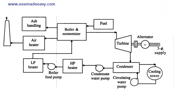
Main flow circuits of Steam power plant Layout
The flow circuit can be divided in to four main circuits.
a) Fuel & Ash circuit.
b) Air & Gas circuit.
c) Feed water & Steam circuit.
d) Cooling water circuit.
a) Fuel & Ash circuit.
Steam can be generated from coal, gas, or oil as the main fuel. Fuel is stored in the storage and fed to the boiler through conveyor belt.
From the storage plant, coal is delivered to the coal handling plant where it is pulverised ( i.e, crushed in to small pieces) , so that complete burning is possible and total energy can be extracted in terms of heat.
It is required to control the heat energy.
Therefore the coal is passed through the crushers, sizers, dryers and magnetic separator before feeding in to the boiler.
The coal is burnt in the boiler and the as produced after the combustion of coal is removed to the ash handling plant and then delivered to the ash storage plant for disposal.
The removal of ash from the boiler furnace is necessary for proper burning of the coal.
During the light up of boiler, it is not possible to burn the coal and therefore liquid fuels are required.
It is also required during the disturbance in boiler because it is easy t o control the energy from liquid fuels.
b) Air & Gas circuit.
Air is required for the complete combustion of the fuel which is supplied through the forced draught (FD) fans and induced draught (ID) fans.
In all large thermal power plants, both fans are used and normally they are in pairs to balance the boiler.
The air, which is fed to the boiler, is passed through the air preheater to extract some energy of flue gases coming out from the boiler after burning the coal. It also helps in the proper burning of of the coal.
The flue gases consists of gases and ash, which are passed through the precipitator (or dust collector) and then finally go to atmosphere through chimney.
c) Feed water & Steam circuit.
If the seam power plant is of condensing type, the steam is converted to water by condenser.
Due to the safety of the turbine, the water used is demineralised (DM) and therefore it is not wasted (to have economic operation of plant).
Some part of steam and water is lost while passing through the different components of the system due to leakages. This can be compensated by adding the makeup water in feed water system.
The boiler feed pump (BFP) feeds the water in to the boiler drum where it is heated to form the steam.
The wet steam from the drum is again heated in super heater, before it is passed to the turbine.
The super heated steam is expanded in the turbine to run it.
Depending upon the size of the power plant unit, where there are different stages of prime mover.
High pressure (HP) turbine.
Intermediate pressure (IP) turbine.
Low pressure (LP) turbine.
The steam after the expansion in HP turbine is sent back to boiler for reheating to increase the temperature and pressure.
After coming out from LP turbine, steam is passed through the condenser in the hot well and finally to boiler through the BFP.

a) Cooling water circuit
To condensate the steam in condenser and maintaining low pressure in it, a large quantity of cooling water is required, which is taken from the river or pondage.
After passing it through the condenser, it is fed back to the river or pondage.
When there is no enough water, the cooling tower or cooling ponds are used.
Main parts of Steam Power Plant
(1). Boiler:-
Ø2nd tallest part after the chimney in a power plant.
Ø Used for producing the steam and reheating the steam.
ØTwo types: water-tube boilers & fire tube boilers
Water-tube boilers
· Generally used.
· Water flows in the tube and fire is outside.
· Low stresses from pressure and temperature differential and small drum size.
· Less weight of metal for a given size.
· Less liable to explode.
· Produce high pressure and quickly controlled steam.
Fire-tube boilers
· Fire flows in the tube and water is outside.
· Cheap, but are more likely to explode.
· Outer shell of the fire tube boiler is more than that of water tube.
Since steam at different pressure and temperature contains varying amount of energy, the no. of Kg steam generated is not an exact measure of the energy produced.
The capacity of steam boiler is expressed as the total heat transferred by the heating surface in BTU per hour.
The heat transfer process that occurs in a steam generator is a steady flow process for which transferred heat is equal to the change in enthalpy of the fluid. The boiler output, as measured by the heat absorbed by water and system is given by,
ms→ weight of steam delivered by boiler, Kg/Hr
hs→ Enthalpy of steam at observed pressure and quality of temperature, BTU/Kg
hf→ Enthalpy of the fluid of feed water at observed condition, as water reaches the boiler, BTU/Kg.
The overall boiler efficiency of a steam generating unit at any operating condition is the ratio of the transferred heat to the energy supplied by the fuel. ie, output divided by input.

mf→ Total weight of fuel fired per hour.(Kg)
F→ High heat value of fuel as fired (BTU/Kg)
(2). Coal Mills
The coal mills are used for drying of coal, grinding, and separation of particles of desired size, forming proper air-fuel ratio and suitable control of all these operations.
The two systems of preparing and burning pulverized fuels are
(a) the central or storage system where one independent plant prepares and transports to all unit and
(b) the unit or direct fire system in which one or more units connected to it.
Preheated forced air passed through pulverizer eliminates the necessity of separate driers.
The fuel is first crushed to a general size(1 cm) and then passed over the magnetic separator to remove the tramp iron such as nuts, bolts and rivets.
This crushed coal goes to the pulverizers and then directly to furnace.
Pulverizers may be divided in to four types based on the method of fuel size reduction, namely
- Ball race
- Bowl mill
- Impact mill
- Ball mill
The advantages of pulverized fuel include
- Complete combustion
- Simpler ash disposal
- Absence of smoke
- Use of cheap fuel
- Equipment adoptable to other fuels (oil and gas)
- Easy control of air & fuel supply
- Absence of all moving parts in the furnace
- No stand by losses
- Lower labour cost
- Increase of capacity per unit furnace volume
- Higher efficiency
Grate and Stokers
Grate:- Grate is a sectional metallic structure designed to support the fuel in a furnace and to permit passage of primary combustion air through openings to the fuel.
Stoker:- Stoker is a power-operated fuel-feeding mechanism. It is used for supplying solid fuel to a furnace and admitting air to the fuel for proper combustion.
By the use of stokers;
· A cheaper grade of fuel can be burned with higher efficiency.
· Greater operational efficiency.
· Better maintenance of furnace.
· Production of less smoke.
Stokers can be;
- Travelling grate
- Overfeed stokers
- Spreader
- Underfeed stokers
(1). Boiler feed pump
A high capacity induction motor is used to feed the water to the boiler. Boiler feed pump is the highest power consuming auxiliaries in the steam power plants.
Feed water:- natural water cannot be used as such for steam generation as it contains solid, liquid and gaseous impurities, which damage the blades of the turbine.
(2). Air preheater
Air preheaters are used to extract heat from the flue gases to the combustion air. The advantages of preheaters are;
- Improved combustion
- Successful burning of low-grade fuel
- Increased efficiency and increased capacity of plant
Air preheaters apply either convection or the regeneration principle of heat transmission.
(3). Draught system
· To supply air to the furnace and to the furnace and to take the flue gases from the boiler through the chimney.
· The pressure difference known as the draft is usually measured in centimeters (cm) of water gauge.
· The resistance to the flow air and flue gases which make the draught system necessary are;
o Ducts, stacks, chimney, fuel beds, dampers, air preheaters, economizers, accumulation of sooth and ashes in gas passages etc.
o Natural draught: if the pressure difference is by chimney or stack.
o Forced draught: fans are used to create pressure difference.
o Two types of fans; forced draught(FD) and induced draught(ID) fans.
(4). Economizers
· Used to extract heat from the flue gases for the heating of feed water.
· They may be placed in the last flue gas pass within the boiler setting or in the casing between the boiler setting and the chimney or stack.
· Economizers increase the resistance to the flow of flue gases and also reduces their temperature and therefore induced draft is required.
(5). Super heaters and Reheaters
The steam that exists at the vaporization temperature corresponding to its absolute pressure is defined as saturated steam, which may or may not carry water with it.
The temperature and total enthalpy of the saturated steam, at any pressure can be increased by the application of additional heat. i.e, super heating.
Advantages of superheating of steam are;
· The additional heat imparted to vapour causes it to behave more likely to perfect gas.
· Steam condensation can be avoided.
· Increases the efficiency.
· Elimination of moisture.
Super heaters are simple heat exchangers for imparting additional energy to steam for a given pressure.
A reheater is essentially a super heater, as it is designed to bring the partially expanded steam back to superheat temperature by passing it through the tubes.
(6). Turbines
Turbine, used to rotate the synchronous alternator is a device which converts steam energy to rotational K.E. and can be classified on the basis of steam flow direction, expansion process, no. Of stages, speed etc.
The P.E in steam due to pressure and internal energy is converted to K.E when passing through the nozzles. In impulsive turbines, the steam expands in the stationary nozzles and attains higher velocity.
There are several stationary blades and moving blades. In reaction turbines, there are no nozzles, but they have also fixed and moving blades.
· The rating of generating unit depends on the rating of turbines.
· Commercial turbines use series combination of impulse and reaction turbines.
· To increase the shaft output, several stages are used (HP, IP and LP turbines). For lower rating of alternator only one stage is used.
Classification of Steam turbines
Basis of classification
a) Expansion process
o Impulse turbine
o Reaction turbine
o Combination of impulse and reaction turbine
b) Steam flow direction
o Axial turbine
o Radial turbine
o Tangential turbine
c) No. Of stages
o Single stage turbine
o Multi stage turbine
§ Velocity compounded impulse (Curtis stage)
§ Pressure compounded impulse (Rateau stage)
§ Pressure-velocity compounded impulse ( Curtis-Rateau stage)
§ Pressure compounded reaction turbine (parson’s stage)
d) No. Of flows
o Single flow
o Double flow
o Divided flow
o Tandem or cross compounded
e) Relative motion of rotor
o Single rotation
o Double rotation
f) Rotational speed
o N= 3000 rpm, f = 50 Hz
o N= 3600 rpm, f = 60 Hz
o N= 1500 rpm, f = 50 Hz
o Geared units
g) Applications
o Electric power generation
o Industrial
o Marine
h) Steam conditions
o High pressure non condensing
o High pressure condensing
o Back pressure
o Regenerative
o Reheating
o Extraction
o Mixed pressure
o Exhaust pressure turbine
(7). Condenser
§ It is a device in which the exhaust steam from engines and turbines is condensed and air and other non condensable gases are removed in a continuous process.
Advantages are;
o To increase the efficiency of plant
o Recovery of condensate for re-use as boiler water
· Two types;
o Surface
o Jet
· Cooling of the surface of condenser is required.
(8). Cooling tower
§ Forms the major section of the condensing system.
§ In closed cooling system, involving the cooling towers, the cooling tower follows a closed cycle through the cooling tower.
§ Types are
o Natural type
o Mechanical draught type
(9). Alternators
§ High speed synchronous generators are used because the efficiency of steam turbines is high at high speed.
§ If ‘P’ is the no. of poles and f is the frequency of the system, the speed (N) in revolution per minute (rpm) is given by,
N= 120f/P
§ Highest possible speed for 50 Hz supply system is 3000 rpm [P=2].
§ For 60 Hz, it is 3600 rpm.
§ Field winding is placed at the rotor and armature winding at the stator.
§ Normally concentric type (involute) and diamond type windings are used for alternators.
Concentric type
o Straight bars are placed in series enclosed slots and separate end connectors are concentrically disposed.
o Yoke is extended at either end to protect the end windings.
o Core conductors are placed in semi enclosed slots ( internal reactance of the machine is high)
o There may be 3 or more coils per slot with graded insulation.
o Concentric windings are preferred in high voltage machine.
Maximum rating of the alternators are 21KV, 500 MW. Other ratings are 11KV, 50MW; 11KV,100/110MW; 15.56 KV, 200/210 MW.
Cooling of Alternators
o Cooling of Alternators is required due to damage of insulation at high temperature.
o Open circuit cooling ( air is drawn by fans and discharged to atmosphere).
o Closed circuit ( fixed volume of H2is re- circulated) is widely used.
Read also :
- General layout of Steam Power Station|Steam power plant parts
- Steam power plants|Steam power generator Plant|Thermal Power Plants
- Rankine cycle|power Cycle for steam power plants
- Energy Efficient Lamps|CFL, LED lamps

- [New] AE KWA Kerala PSC 2026
- [New] Electricity Worker KSEB Syllabus 2026|021/2026 Syllabus Kerala PSC
- [Latest]KWA Operator Syllabus 2026|734,735/2025 Kerala PSC syllabus
- [New]Inspector of Legal Metrology Syllabus|613/2025 Kerala PSC Syllabus
- [PDF]IE Rules|Indian Electricity Rules 1956
- [Latest]Syllabus Sub Engineer LSGD Electricity Wing Thrissur Corporation| 770/2025 Syllabus Kerala PSC
- Compensating Windings
- Transformers Electrical Engineering Interview Questions
- DC Motor Electrical Engineering Interview Questions
- Special Electrical Machines Interview Questions
- 125 Electrical Engineering Interview Questions