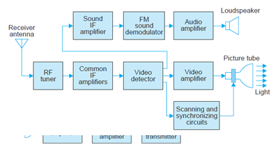
TV receiver
The receiving antenna intercepts the radiated picture and sound carrier signals and feeds them to the RF tuner . The receiver is of the heterodyne type and employs two or three stages of intermediate frequency (IF) amplification.
Read: Television (TV) Basics|History of Television
The output from the last IF stage is demodulated to recover the video signal. This signal that carries the picture information is amplified and coupled to the picture tube which converts the electrical signal back into picture elements of the same degree of black and white.
The picture tube shown in Fig. below is very similar to the cathode-ray tube used in an oscilloscope

The glass envelope contains an electron gun structure that produces a beam of electrons aimed at the fluorescent screen. When the Electron beam strikes the screen, light is emitted. The beam is deflected by a pair of deflecting coils mounted on the neck of the picture tube in the same way and rate as the beam scans the target in the camera tube.
Read: Picture transmission in TV -part 2
Join EEE Made Easy Telegram channel
The amplitudes of the currents in the horizontal and vertical deflecting coils are so adjusted that the entire screen, called raster, gets illuminated because of the fast rate of scanning.
The video signal is fed to the grid or cathode of the picture tube. When the varying
signal voltage makes the control grid less negative, the beam current is increased, making the
spot of light on the screen brighter. More negative grid voltage reduces the brightness. If the
grid voltages is negative enough to cut-off the electron beam current at the picture tube there
will be no light. This state corresponds to black. Thus the video signal illuminates the fluorescent screen from white to black through various shades of grey depending on its amplitude at any instant. This corresponds to the brightness changes encountered by the electron beam of the camera tube while scanning the picture details element by element. The rate at which the spot of light moves is so fast that the eye is unable to follow it and so a complete picture is seen because of the storage capability of the human eye.
Sound reception
The path of the sound signal is common with the picture signal from antenna to the video detector section of the receiver. Here the two signals are separated and fed to their respective channels. The frequency modulated audio signal is demodulated after at least one stage of amplification. The audio output from the FM detector is given due amplification before feeding it to the loudspeaker.
Synchronization
It is essential that the same coordinates be scanned at any instant both at the camera tube target plate and at the raster of the picture tube, otherwise, the picture details would split and get distorted. To ensure perfect synchronization between the scene being televised and the picture produced on the raster, synchronizing pulses are transmitted during the retrace, i.e., fly-back intervals of horizontal and vertical motions of the camera scanning beam. Thus, in addition to carrying picture detail, the radiated signal at the transmitter also contains
synchronizing pulses. These pulses which are distinct for horizontal and vertical motion control, are processed at the receiver and fed to the picture tube sweep circuitry thus ensuring that the receiver picture tube beam is in step with the transmitter camera tube beam.
Receiver controls

The front view of a typical monochrome TV receiver, having various controls is shown in Fig. The channel selector switch is used for selecting the desired channel. The fine tuning control is provided for obtaining best picture details in the selected channel.
The hold control is used to get a steady picture in case it rolls up or down. The brightness control varies the beam intensity of the picture tube and is set for optimum average brightness of the picture. The contrast control is actually the gain control of the video amplifier.
Join EEE Made Easy Whatsapp Channel
This can be varied to obtain the desired contrast between the white and black contents of the reproduced picture. The volume and tone controls form part of the audio amplifier in the sound section, and are used for setting the volume and tonal quality of the sound output from the loudspeaker.
More on TV- Television
- Television (TV) Basics|History of Television
- Picture and Sound transmission in TV – part 1
- Picture transmission in TV -part 2
- Picture and Sound reception in TV
Latest Posts in EEE Made Easy
- Compensating Windings
 Compensating Windings: Compensating Windings are used for large direct current machines which are subjected to large fluctuations in load i.e. … Read more
 - Transformers Electrical Engineering Interview QuestionsTransformers Electrical Engineering Interview Questions: QUESTIONS AND ANSWERS ON TRANSFORMERS Read: 125 Electrical Interview Questions Q.1. How is magnetic leakage … Read more
- DC Motor Electrical Engineering Interview QuestionsDC Motor Electrical Engineering Interview Questions: DC Motor Interview Questions and answers. Read: 125 Electrical Interview Questions Q. 1. How … Read more
- Special Electrical Machines Interview QuestionsSpecial Electrical Machines Interview Questions: Electrical Interview Questions Read: Electrical Interview Q.1. Do stepper motors have internal or external fans? … Read more
- 125 Electrical Engineering Interview QuestionsElectrical Engineering Interview Questions: Read 125 Questions based on Electrical Interview Questions. 1) What is Electrical Engineering? Electrical Engineering … Read more
- Syllabus Training Instructor Plumber|14/2025 Syllabus Kerala PSCSyllabus Training Instructor Plumber: 14/2025 Syllabus Kerala PSC. Download the syllabus and Previous question papers for the Training Instructor in … Read more
- [PDF] Syllabus AE KSEB Transfer|378/2025 Syllabus Kerala PSCSyllabus AE KSEB Transfer: DETAILED SYLLABUS FOR THE POST OF ASSISTANT ENGINEER(ELECTRICAL) (Kerala State Electricity Board Ltd.) – By Transfer … Read more