Transmission tower design: Electrical Tower is modeled using constant parameters such as height, bracing system, angle sections, base widths, wind zone, common clearances, span, conductor and ground wire specifications.The loads are calculated using IS: 802(1995)
- Types of Transmission Towers|Electrical Tower Types
- Transmission structures|Transmission towers and Transmission Poles|Electric Tower
- Parts of a Power transmission line and Transmission tower|Transmission tower parts
Transmission tower design
The Transmission line towers are one of the important life line structures in the distribution of power from the source to the various places for several purposes. The tower is designed for the wind zone V carrying 132 KV DC.
Types of Towers
The types of towers based on their constructional features, which are in use on the power transmission lines are
given below.
Self-Supporting Towers
Conventional Guyed Towers
Chainette Guyed Towers
Self-Supporting Towers:
Self-supporting towers are covered under Indian Standard (IS: 802) and other National
and International Standards.
These fabricated, using tested quality mild steel structural‟s or a combination of tested
quality mild steel and High tensile structural‟s conforming to IS: 2062 and IS:8500 respectively.
Conventional Guyed Towers
Conventional Guyed Towers are the towers comprise portal structures fabricated in „Y‟ and „V‟ shapes and have been used in some of the countries for EHV transmission lines up to 735 kV.
The guys may be internal or external.
The guyed tower including guy anchors occupy much larger land as compared to selfsupporting towers and as such .This type of construction finds application in long unoccupied, waste land.
Chainette Guyed Tower
Chainette Guyed Tower is similar to that of guyed towers but carrying double circuit lines.
Tower design
- Tower width
- Base width
- Top damper width
- Cross arms length
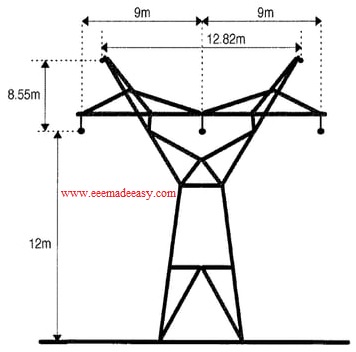
Height of Tower Structure
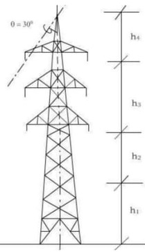
Height of tower “H” ts determined by;
H =h1+h2+h3+h4
h1=Minimum permissible ground clearance
h2=Maximum sag
h3=Vertical spacing between conductors
h4 =Vertical clearance between earthwire and top conductor
base width design
The base width(at the concrete level) is the distance between the centre of gravity at one corner leg and
the centre of gravity of the adjacent corner leg.
A particular base width which gives the minimum total cost of the fower and foundations.
Ryle formula
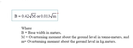
The ratio of base width to total tower height for most towers is generally about one-fifth to one-tenth.
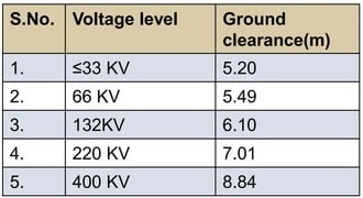
Ground Clearance of Tower
Ground clearance,
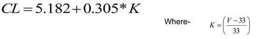
Minimum permissible clearance
transmission tower minimum permissible clearance as per IE Rule 1956, rule 77(4)
CONDUCTOR
A substance or a material which allows the electric current to pass through its body when it is subjected to a difference of electric potential is known as Conductor.
The materials which are used as conductors for over head transmission lines should have the following electrical and physical properties.
- It should have a high conductivity
- It should have tensile strength.
- It should have a high melting point and thermal stability.
- It should be flexible to permit us to handle easily and to transport to the site easily.
- It should be corrosion resistance.
ACSR CONDUCTORS
Aluminium has an Ultimate Tensile Strength (U.T.S) of 16 – 20 kg / mm2 where as the steel has a U.T.S of about 136 kg / mm2.
By a suitable combination of steel and aluminium the tensile strength of the conductor is increased greatly.
Thus, there came into use the Aluminium Conductor Steel Reinforced (ACSR).
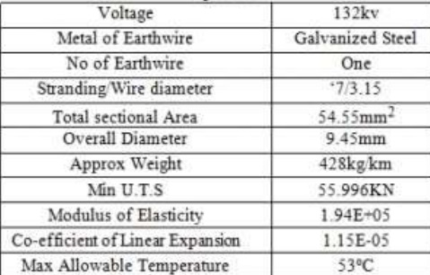
EARTH WIRE
The earth wire is used for protection against direct lightning strokes and the high voltage surges resulting there from.
There will be one or two earth wire depending upon the shielding angle or protection angle.
The earth wire to be used for transmission line is ,
Download & Install EEE Made Easy App
- Types of Transmission Towers|Electrical Tower Types
- Transmission structures|Transmission towers and Transmission Poles|Electric Tower
- Parts of a Power transmission line and Transmission tower|Transmission tower parts
Latest Posts in EEE Made Easy
- Energy Efficient Lamps|CFL, LED lamps
 Energy Efficient Lamps: CFL (Compact Fluorescent lamp ) and LED (light emitting diodes) lamp are Energy Efficient Lamps. Energy Efficient … Read more
 - [New] AE KWA Kerala PSC 2026AE KWA Kerala PSC 2026: DETAILED SYLLABUS FOR SELECTION TO THE POST OF ASSISTANT ENGINEER IN KERALA WATER AUTHOERITY AE … Read more
- [New] Electricity Worker KSEB Syllabus 2026|021/2026 Syllabus Kerala PSCElectricity Worker KSEB Syllabus 2026- 021/2026 Syllabus Kerala PSC: DETAILED SYLLABUS FOR THE POST OF ELECTRICITY WORKER IN KERALASTATE ELECTRICITY … Read more
- [Latest]KWA Operator Syllabus 2026|734,735/2025 Kerala PSC syllabusKWA Operator Syllabus 2026 – 734,735/2025 Kerala PSC syllabus: KERALA PUBLIC SERVICE COMMISSIONDETAILED SYLLABUS FOR THE POST OF OPERATOR (DIRECT) … Read more
- [New]Inspector of Legal Metrology Syllabus|613/2025 Kerala PSC SyllabusInspector of Legal Metrology Syllabus– 613/2025 Kerala PSC Syllabus: DETAILED SYLLABUS FOR THE POST OF INSPECTOR OF LEGAL METROLOGY IN … Read more
- [PDF]IE Rules|Indian Electricity Rules 1956IE Rules:The Indian Electricity Rules 1956 was made under section 37 of the Indian Electricity Act, 1910 and redefined after … Read more
- [Latest]Syllabus Sub Engineer LSGD Electricity Wing Thrissur Corporation| 770/2025 Syllabus Kerala PSCSyllabus Sub Engineer LSGD Electricity Wing Thrissur Corporation: DETAILED SYLLABUS FOR THE POST OF SUB ENGINEER IN LSGD(ELECTRICITY WING OF … Read more