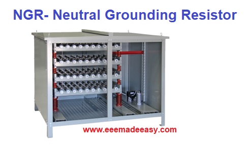
Neutral Grounding Resistor: NGR Full form is Neutral grounding resistor. Neutral grounding resistors (NGRs) or Neutral earthing resistors (NERs) are used for the grounding of electric power systems to provide ground fault, overvoltage, and short circuit protection.
An NGR (Neutral grounding Resistor) is used to limit ground fault currents to safe levels so that all the electrical equipment in a power system is protected. NGRs are also called Neutral Earthing resistors (NER) and Earth protection Resistors (EPR).
A Neutral Grounding Resistor system can be inserted between the neutral and ground in a power system for ground fault protection.
What is NGR?
NGR Full form is Neutral grounding resistor. Neutral grounding resistors (NGRs) or Neutral earthing resistors (NERs) are used for the grounding of electric power systems to provide ground fault, overvoltage, and short circuit protection.
NGR or Neutral Grounding Resistors are used in generating stations, with power transformers and with long-line shunt reactors to limit the fault current to prevent unwanted current damages.
Neutral Grounding Resistors are employed in AC distribution networks to limit fault current that flows from the transformer or generator neutral star point in the event of an earth fault in a system.
Download & Install EEE Made Easy App
Neutral Grounding Resistors are used when the neutral of the supply is accessible and its own impedance is not enough to limit fault current.
Application/Use of Neutral Grounding Resistor
- NGR systems are used in substations within the oil & gas, industrial, and utility markets
- Neutral Grounding Resistors are integrated with medium-voltage generators and large power transformers in which the neutral grounding resistor is located between the system’s neutral and ground.
DIGITAL EARTH TESTER WITH CALIBRATION CERTIFICATE
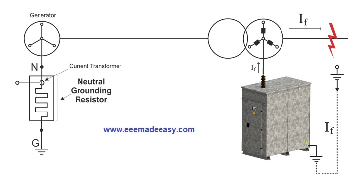
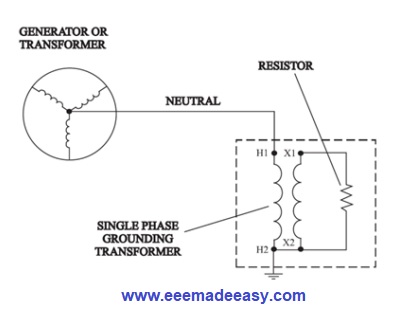
NGR connection diagram
NGR Connection diagram is given below.

Types of Grounding
- System grounding
- Neutral grounding
System Grounding
The process of connecting some electrical part of the power system (e.g. neutral point of a star
a connected system, one conductor of the secondary of a transformer etc.) to earth (i.e. soil) is
called system grounding
Neutral Grounding
The process of connecting neutral point of 3-phase system to earth (i.e. soil) either directly or
through some circuit element (e.g. resistance, reactance etc.) is called neutral grounding.
Neutral grounding provides protection to personal and equipment.
It is because during earth fault, the current path is completed through the earthed neutral and the protective devices (e.g. a fuse etc.) operate to isolate the faulty conductor from the rest of the system.
Methods of Neutral Grounding
The methods commonly used for grounding the neutral point of a 3-phase system are:
(i) Solid or effective grounding.
(ii) Resistance grounding.
(iii) Reactance grounding.
(iv) Peterson-coil grounding.
The choice of the method of grounding depends upon many factors including the size of the
system, system voltage and the scheme of protection to be used.
Read : Difference between earthing and grounding
Resistance Grounding
In order to limit the magnitude of earth fault current, it is a common practice to connect the
neutral point of a 3-phase system to earth through a resistor. This is called resistance grounding.
When the neutral point of a 3-phase system (e.g. 3-phase generator, 3-phase transformer etc.) is connected to earth (i.e. soil) through a resistor, it is called resistance grounding.
Why to use a Neutral Grounding Resistor?
Typically, NGRs are used with generators or motors.
With generators or motors, ground fault currents can be extremely high and if its is not controlled, it can result in damage to transformers, generators, motors, wiring, and associated equipment.
Neutral Grounding Transformers
Neutral grounding resistors for generators
Neutral grounding resistors for generators will avoid damaging the stator core from fault currents. Stator cores are made of silicon steel laminations, cold-rolled or grain-oriented steel. etc.
If damage were to occur to the Stator core it could result in the complete replacement of the motor/generator or a costly off-site repair.
To limit the damage to the core, generator and motor manufacturers allow for a limited ground fault current, which is usually provided by the manufacturer in terms of Core Damage Curves.
By inserting a Neutral Ground Resistor (NGR) between the system neutral and ground, it lowers the prospective ground-fault current to a predetermined value.
NGR will Control the magnitude of the ground fault currents and it will reduce the stress and amount of damage to your power system equipment.
By connecting an NGR to the neutral of a generator, it will limit the amount of the generator available Line to Neutral fault current to below the design limits of generators.
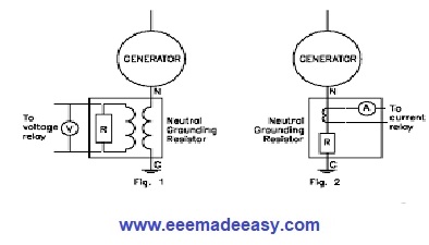
Another advantage of a Neutral Earthing Resistor system is that ground fault current can flow, permitting it to be detected and measured.
NGR Resistance value calculation
Depending on the application, the resistor can be designed for either a high or low current value, or continuous or a predetermined duration.
The NGR resistance value must be selected on the basis of the following factors.
- The system voltage
- The system capacitance current: During an earth fault, the the system capacitance current will also get discharged through the NGR. The selected NGR value is selected such as to handle this current.
- The resistance value must be selected such that the tripping relay must sense the fault current. If a very high NGR resistance value is selected, then the relay may not sense the fault current.
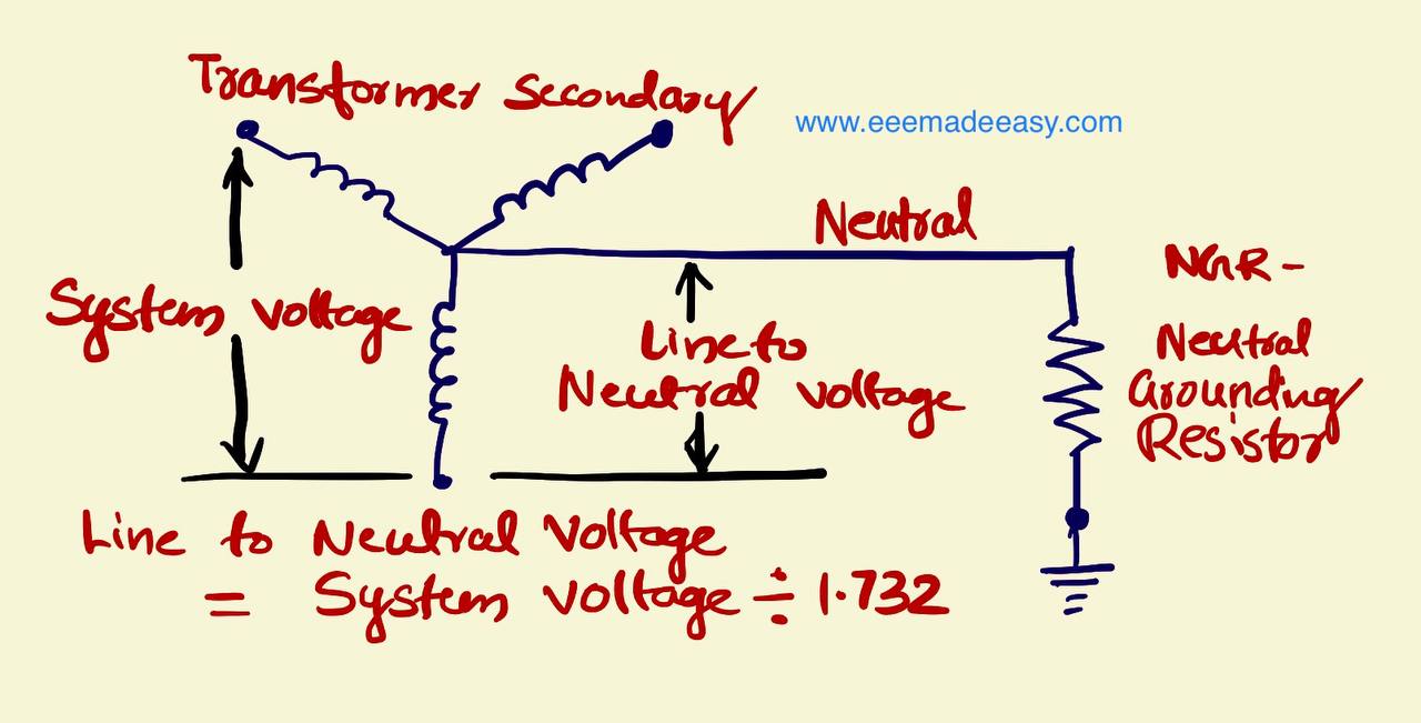
The value of NGR resistance is;
R = VLN/ If
= (VLL/√3) /If
Example for NGR resistance value selection
The transformer’s secondary voltage is 6.6 KV and the transformer full load current is 900 Amps.
The line to neutral voltage is
VLN = 6600/√3 = 6600/1.732 =3810 Volts
The full load secondary current of the transformer is 900 amperes.
So, the resistance value required to limit the fault current to the transformer’s maximum current carrying capacity is calculated as given below.
R = V/I
R = VLN / I
R= 3810/900
R= 4.23 Ω
NGR Resistance Specifications
- Location: Indoor/Outdoor
- Cooling : Air Natural(AN) cooling
- Ambient Temperature : 50° C
- Rated Voltage: the phase voltage of the system
- Rated Current: the full load secondary current of transformer
- Allowable tolerance in NGR resistance : +/- 10 %
- Temperature rise: 375° C
- Time rating: 10 Seconds
How do you calculate NGR size?
Here are some parameters to consider when choosing and sizing an NGR
• Rated Line-to-Line voltage or Line-to-Neutral voltage.
• Time duration of the NGR will carry the maximum current.
• Short time rating: typically, 10 seconds or 60 seconds.
• Continuous rating: normally 5% to 10 % of full load current.
• Maximum current when the resistor is cold.
• Insulation specified based on line voltage.
• The maximum short time temperature rise for the resistive element is 760°C, in accordance with IEEE Standard 32-1972 (Requirements, Terminology and Test Procedure for Neutral Grounding Devices).
• Ingress protection IP rating for outdoor or indoor enclosures. Standard enclosures are manufactured having IP10, IP13 or IP23.
• Enclosure material can be mild steel, finished in powder coat or hot-dip galvanized, or Stainless-steel.
• Auxiliary items: Voltage transformers, off-load isolators, current transformers, or other options.
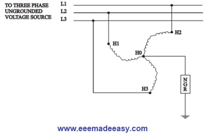
Neutral Grounding Resistor System Example
Below is an example of an NGR system from Megaresistors.
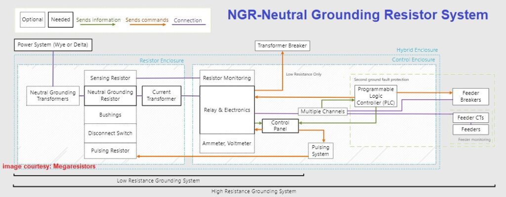
The above MegaResistors diagram displays how Neutral Grounding Resistors work in a system, and how their functionality can be extended.
Neutral Grounding Resistors are used in general to ground Transformers or Generators with Delta or Wye secondaries.
If Delta, a Neutral Grounding Transformer is used to create a Neutral point.
In both cases, a Neutral Grounding Transformer can be used to reduce the voltage applied to the NGR.
The NGR is connected to the neutral point and can have additional features such as:
- Sensing resistors, allow resistor monitoring.
- Bushings, allow for ease of connection with external ground and neutral insulated conductors.
- Pulsing resistors, speed up the location of the ground fault.
- Other components, such as a disconnect switch.
The neutral is passed through a current transformer, which will be connected to a ground fault protection relay.
The relay has the primary function of detecting ground faults.
Detected values can be displayed on metering devices (Ammeter, Voltmeters).
If a ground fault is detected
Low resistance: The relay will trips the breaker.
High resistance: The relay will activate an alarm, there is no need to trip.
The relay can also send information to the logic controller if using second-ground fault protection.
Lamps on the control panel provide important information from the relay.
There are numerous functions on the control panel that allow staff to control the system.
One of these functions is the pulsing system, which activates the pulsing resistor.
If using second ground fault protection, the logic controller will control and assign priorities to feeders.
- It will send commands to the relays to control the system.
- It will send information to the control panel to display.
Anything in the low-resistance bracket shows what a low-resistance system is capable of. Anything in the high-resistance bracket shows what a high-resistance system is capable of.
These features and components can be enclosed in two separate (resistor and controls) enclosures, or in a single enclosure.
Depending on the voltage class, or if using a second ground fault protection system, only separate enclosures are allowed.
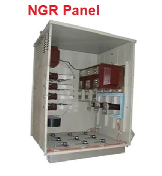
NGR panel
TECHNICAL SPECIFICATION FOR NEUTRAL GROUNDING RESISTOR
The material, constructional features and various processes involved in manufacture shall comply with latest revision of Indian Standards.
Read : [Updated]List of IS Codes Electrical standards|IS 732, IS 3043 etc|Indian electrical standards
The design, material, construction, manufacture, inspection, testing and performance of Neutral Grounding Resistor shall conform to the latest revision of relevant standards and codes of practices.
In case of conflict between the applicable reference standard and this specification, this specification shall govern.
Design Requirements and Constructional Features of NGR
- The NGR is used for medium resistance grounding of MV (11 / 6.6 / 3.3KV) or LV (415 V) system. NGR shall be connected between earth pit and neutral point of applicable transformer.
- The NGR shall be suitable for limiting the desired value of earth fault current and duty as specified in BOQ-Cum-Price Schedule in NIT.
- The resistor unit shall be natural air-cooled type suitable for installation at outdoor/ indoor locations.
- The NGR will be installed in hot humid and tropical atmosphere. All equipment, accessories and wiring shall be provided with tropical finish to prevent fungus growth.
- Each Neutral Grounding Resistor shall be formed of non-aging (grade ASTM-A240/AISI-304 or better) corrosion resistant punched stainless steel elements or FECRAL (AISI-406) as specified in data sheet-A for high value (say 300A/400/500A) of earth fault current and of FECRAL (AISI-406) material for low value (say 1A) of earth fault current.
- Resistance material mentioned above shall have high electrical resistivity and low temperature co-efficient of resistance.
- Resistor bank shall be provided in series and parallel combination to achieve the overall resistance value. Minimum two banks in parallel shall be provided in the system, unless specified otherwise.
- The resistor unit shall consist of suitable no. of elements. All the elements shall be mounted inside the cubicle so as to ensure ease of inspection and replacement of individual element. For Low value of earth fault current edge wound configuration of resistance material is also acceptable.
- Each resistor element shall possess a balanced combination of both Mechanical and Electrical properties over entire intended operating temperature range without any harmful effect on the elements and their accessories.
- All the resistor elements consisting the NGR shall be assembled and supported inside the cubicle in such a way that no distortion or breakage will occur during the passage of specified fault current to earth.
- All elements connection shall be bolted type to ensure stable resistance value throughout the working life of the unit.
- Wet process type brown glass porcelain insulators shall be used between Tie-rod and end support structure and shall also be used to insulate the resistor bank from enclosure. Porcelain insulators shall have high creepage value suitable for heavily polluted atmosphere charged with dust particles. Interposing insulator (except Mica) shall be provided to insulate resistor tier.
- The resistor elements shall be provided with necessary installations and shall have maximum temperature rise .
- The NGR shall be provided with suitable taps for cable/strip connection.
- In case the connection between the neutral terminal of transformer and NGR is through a copper strip, then copper strip shall be supplied by bidder. The required hardware for the termination of copper flat at both ends shall be supplied by the bidder
NGR Enclosure
- Each neutral grounding resistor shall be housed in weather-proof enclosure having Degree of Protection as specified in Data Sheet-A. Enclosure shall be cold rolled sheet steel having a minimum thickness of 2 mm. Suitable ventilating louvers shall be provided on sides to ensure proper ventilation. The louvers shall be provided with fine wire mesh to
make vermin proof. - The terminals for neutral and earthing connections shall be housed in separate vermin-proof, weather-proof terminal box with min. IP-55 degree of ingress protection.
- A separate canopy shall be provided above enclosure roof with a suitable air gap between them. It shall also cover the terminal compartment. Suitable lifting arrangement shall be provided to lift the canopy.
- The bottom of the enclosure shall be provided with a drain plug to remove water that may get collected in the enclosure.
- The enclosure shall be supported on insulators placed on mounting structure in such a fashion that it is not easily accessible for man standing on ground level. Any part of insulator shall be at a height 2500 mm above ground/plinth.
- Each cubicle shall be complete with front access door with handles, lock and also a removable bolted cover. All doors and removable covers shall be properly gasketed with good quality neoprene /synthetic rubber gaskets.
- All cubicle door hinges shall be concealed type. Each cubicle shall be complete with suitably mounted cable box fitted with removable gland plate of Aluminium of suitable thickness for fixing cable gland. Double compression brass Cable glands and cable lugs of tinned copper shall be in the scope of bidder.
- All necessary galvanised bolts, nuts washers etc. shall be included by the BIDDER for installation of Cubicle at site.
- The enclosure shall not be earthed to prevent bypassing of resistor in case of any inadvertent shorting of resistor from inside.
- Panel space heater arrangement along with thermostat, suitable for connection to 240V AC single supply, shall be provided at the bottom of the panel. The illumination arrangement and switch socket shall also be provided in the panel. The required cable glands, lug etc. required shall be supplied by the bidder.
- For connection of other end of NGR to ground, Tinned copper flat (of size 50mm x 6mm) with Fork connector up to 300mm above ground with 2 nos. earthing terminal/pad, tapped holes and bolts suitable for Connection of GS Flat shall be provided by Bidder. The tinned copper flat shall be insulated from the mounting structure through porcelain insulators.
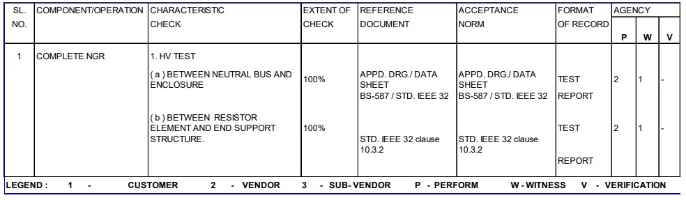
NGR INSPECTION & TESTS
- All tests shall be conducted as per relevant IS/IEC/ IEEE standards
- Type Test certificates (temperature rise and DOP tests)
Following tests shall also be conducted in addition to those mentioned in Quality plan
Advantages of Neutral Grounding
The following are the advantages of neutral grounding :
(i) Voltages of the healthy phases do not exceed line to ground voltages i.e. they remain nearly
constant
(ii) The high voltages due to arcing grounds are eliminated.
(iii) The protective relays can be used to provide protection against earth faults. In case earth
fault occurs on any line, the protective relay will operate to isolate the faulty line.
(iv) The over voltages due to lightning are discharged to earth.
(v) It provides greater safety to personnel and equipment.
(vi) It provides improved service reliability.
(vii) Operating and maintenance expenditures are reduced.
What is NGR Full form?
NGR Full form is Neutral Grounding Resistor
What is ngr?
NGR or Neutral grounding resistor used to connect neutral of transformers or alternators for fault current protection
What is another name for NGR?
Another nae for NGR is NER (Neutral Earth Resistor)
What is Ngr full form electrical?
Neutral Grounding Resistor
Ngr calculation
The value of NGR resistance is; R = VLN/ If
= (VLL/√3) /If
Where is neutral grounding resistor used?
neutral grounding resistor used with generators and transformers in power system
Neutral Ground Resistor Calculation For Transformer
The value of NGR resistance is R = VLN/ If
= (VLL/√3) /If
Latest Posts in EEE Made Easy
- Energy Efficient Lamps|CFL, LED lamps
 Energy Efficient Lamps: CFL (Compact Fluorescent lamp ) and LED (light emitting diodes) lamp are Energy Efficient Lamps. Energy Efficient … Read more
 - [New] AE KWA Kerala PSC 2026AE KWA Kerala PSC 2026: DETAILED SYLLABUS FOR SELECTION TO THE POST OF ASSISTANT ENGINEER IN KERALA WATER AUTHOERITY AE … Read more
- [New] Electricity Worker KSEB Syllabus 2026|021/2026 Syllabus Kerala PSCElectricity Worker KSEB Syllabus 2026- 021/2026 Syllabus Kerala PSC: DETAILED SYLLABUS FOR THE POST OF ELECTRICITY WORKER IN KERALASTATE ELECTRICITY … Read more
- [Latest]KWA Operator Syllabus 2026|734,735/2025 Kerala PSC syllabusKWA Operator Syllabus 2026 – 734,735/2025 Kerala PSC syllabus: KERALA PUBLIC SERVICE COMMISSIONDETAILED SYLLABUS FOR THE POST OF OPERATOR (DIRECT) … Read more
- [New]Inspector of Legal Metrology Syllabus|613/2025 Kerala PSC SyllabusInspector of Legal Metrology Syllabus– 613/2025 Kerala PSC Syllabus: DETAILED SYLLABUS FOR THE POST OF INSPECTOR OF LEGAL METROLOGY IN … Read more
- [PDF]IE Rules|Indian Electricity Rules 1956IE Rules:The Indian Electricity Rules 1956 was made under section 37 of the Indian Electricity Act, 1910 and redefined after … Read more
- [Latest]Syllabus Sub Engineer LSGD Electricity Wing Thrissur Corporation| 770/2025 Syllabus Kerala PSCSyllabus Sub Engineer LSGD Electricity Wing Thrissur Corporation: DETAILED SYLLABUS FOR THE POST OF SUB ENGINEER IN LSGD(ELECTRICITY WING OF … Read more