Types of Lightning Arresters: There are several lightning arrester types in general use. They differ only in constructional details, but operate on the same principle viz. providing low resistance path for the surges to the ground. Lets check each of the Lightning Arrester Types in detail.
Read Also: Lightning Arrester
Lightning Arrester Types
The main types of lightning arresters are;
- Rod gap arrester
- Horn gap arrester
- Multigap arrester
- Expulsion type lightning arrester
- Valve type lightning arrester
Download & Install EEE Made Easy App
Rod Gap lightning Arrester
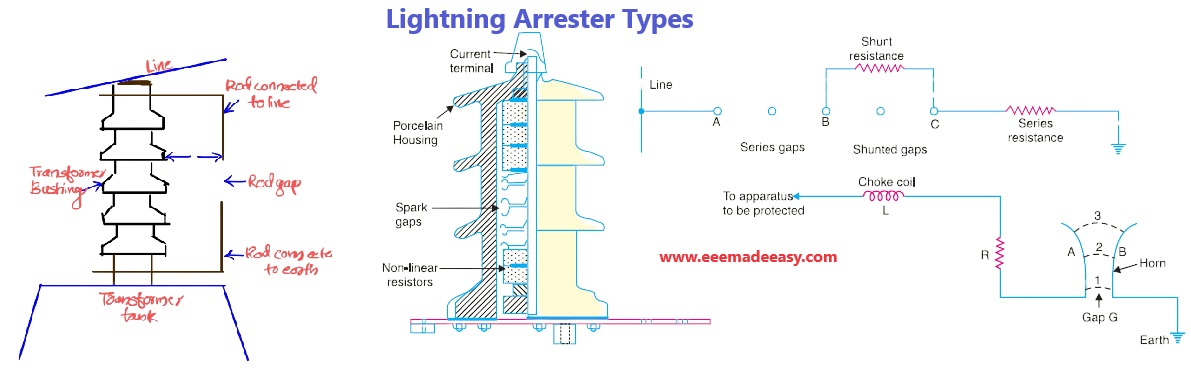
Rod gap arrester is a very simple type of diverter and consists of two 1·5 cm rods which are bent at right angles with a gap inbetween as shown in Fig below.
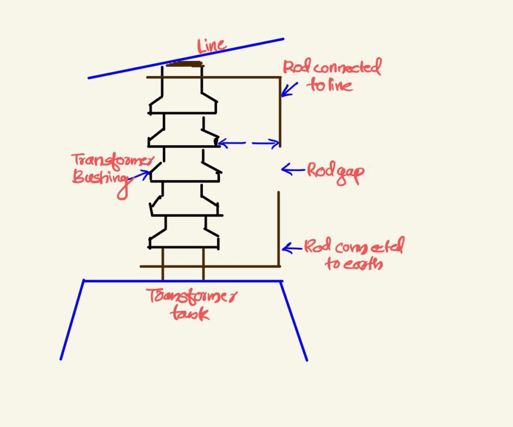
One rod is connected to the line circuit and the other rod is connected to earth.
The distance between gap and insulator (i.e. distance P) must not be less than one-third of
the gap length so that the arc may not reach the insulator and damage it.
Generally, the gap length is so adjusted that breakdown should occur at 80% of spark- over voltage in order to avoid cascading of very steep wave fronts across the insulators.
The string of insulators for an overhead line on the bushing of transformer has frequently a rod
gap across it.
Rod gap arrester working
the above given fig shows the rod gap across the bushing of a transformer.
Under normal operating conditions, the gap remains non-conducting.
On the occurrence of a high voltage surge on the line, the gap sparks over and the surge current is conducted to earth.
In this way, excess charge on the line due to the surge is harmlessly conducted to earth.
Limitations of Rod gap arrester
(i) After the surge is over, the arc in the gap is maintained by the †normal supply voltage,
leading to a short-circuit on the system.
(ii) The rods may melt or get damaged due to excessive heat produced by the arc.
(iii) The climatic conditions (e.g. rain, humidity, temperature etc.) affect the performance of
rod gap arrester.
(iv) The polarity of the surge also affects the performance of this arrester.
Due to the above limitations, the rod gap arrester is only used as a ‘back-up’ protection in case of main arresters.
Horn Gap lightning Arrester
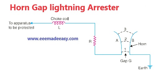
the above fig shows the horn gap arrester.
It consists of two horn shaped metal rods A and B separated by a small air gap.
The horns are so constructed that distance between them gradually increases towards the top as shown.
The horns are mounted on porcelain insulators.
One end of horn is connected to the line through a resistance R and choke coil L while the other end is effectively grounded.
The resistance R helps in limiting the follow current to a small value.
The choke coil is so designed that it offers small reactance at normal power frequency but a very high reactance at transient frequency.
Thus the choke does not allow the transients to enter the apparatus to be protected.
The gap between the horns is so adjusted that normal supply voltage is not enough to cause an arc across the gap.
working of horn gap arrester
Under normal conditions, the gap is non-conducting i.e. normal supply voltage is insufficient to
initiate the arc between the gap.
On the occurrence of an overvoltage, spark-over takes place across the *small gap G.
The heated air around the arc and the magnetic effect of the arc cause the arc to travel up the gap.
The arc moves progressively into positions 1, 2 and 3. At some position of the arc (perhaps position 3), the distance may be too great for the voltage to maintain the arc.
Consequently, the arc is extinguished.
The excess charge on the line is thus conducted through the arrester to the ground.
Advantages of horn gap arrester
(i) The arc is self-clearing. Therefore, this type of arrester does not cause short-circuiting of
the system after the surge is over as in the case of rod gap.
(ii) Series resistance helps in limiting the follow current to a small value.
Limitations of horn gap arrester
(i) The bridging of gap by some external agency (e.g. birds) can render the device useless.
(ii) The setting of horn gap is likely to change due to corrosion or pitting. This adversely
affects the performance of the arrester.
(iii) The time of operation is comparatively long, say about 3 seconds. In view of the very short
operating time of modern protective gear for feeders, this time is far long.
Due to the above limitations, this type of arrester is not reliable and can only be used as a second line of defence like the rod gap arrester.
Multigap lightning arrester
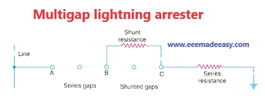
The above fig shows the multigap arrester.
It consists of a series of metallic (generally alloy of zinc) cylinders insulated from one another and separated by small intervals of air gaps.
The first cylinder (i.e. A) in the series is connected to the line and the other to the ground
through a series resistance.
The series resistance limits the power arc.
By the inclusion of series resistance, the degree of protection against travelling waves is reduced.
In order to overcome this difficulty, some of the gaps (B to C in Fig) are shunted by a resistance.
working of multigap arrester
Under normal conditions, the point B is at earth potential and the normal supply voltage is unable to break down the series gaps.
On the occurrence of an overvoltage, the breakdown of series gaps A to B occurs.
The heavy current after breakdown will choose the straight – through path to earth via the
shunted gaps B and C, instead of the alternative path through the shunt resistance.
When the surge is over, the arcs B to C go out and any power current following the surge is limited by the two resistances (shunt resistance and series resistance) which are now in series.
The current is too small to maintain the arcs in the gaps A to B and normal conditions are restored.
Such arresters can be employed where system voltage does not exceed 33 kV.
Expulsion type lightning arrester
This type of arrester is also called ‘protector tube’ and is commonly used on system operating at voltages upto 33 kV.
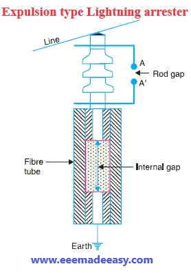
The above fig shows the essential parts of an expulsion type lightning arrester.
It essentially consists of a rod gap A A′ in series with a second gap enclosed within the fibre tube.
The gap in the fibre tube is formed by two electrodes.
The upper electrode is connected to rod gap and the lower electrode to the earth.
One expulsion arrester is placed under each line conductor.
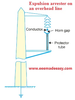
The above fig shows the installation of expulsion arrester on an overhead line.
working of expulsion type lightning arrester
On the occurrence of an overvoltage on the line, the series gap A A′ is spanned and an arc is
struck between the electrodes in the tube.
The heat of the arc vaporises some of the fibre of tube walls, resulting in the production of a neutral gas.
In an extremely short time, the gas builds up high pressure and is expelled through the lower electrode which is hollow.
As the gas leaves the tube violently, it carries away ionised air around the arc.
This de-ionising effect is generally so strong that arc goes out at a current zero and will not be re-established.
Advantages of expulsion type lightning arrester
(i) They are not very expensive.
(ii) They are improved form of rod gap arresters as they block the flow of power frequency
follow currents.
(iii) They can be easily installed
Limitations of expulsion type lightning arrester
(i) An expulsion type arrester can perform only limited number of operations as during each
operation some of the fibre material is used up.
(ii) This type of arrester cannot be mounted in an enclosed equipment due to the discharge of
gases during operation.
(iii) Due to the poor volt/amp characteristic of the arrester, it is not suitable for the protection of
expensive equipment.
Valve type lightning arrester
Valve type arresters incorporate non-linear resistors and are extensively used on systems operating at high voltages.
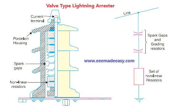
The above shows the various parts of a valve type arrester.
It consists of two assemblies (i) series spark gaps and (ii) non-linear resistor discs (made of material such as thyrite or metrosil) in series.
The non-linear elements are connected in series with the spark gaps.
Both the assemblies are accommodated in tight porcelain container.
(i) The spark gap is a multiple assembly consisting of a number of identical spark gaps in
series. Each gap consists of two electrodes with a fixed gap spacing.
The voltage distribution across the gaps is linearised by means of additional resistance elements (called grading resistors) across the gaps.
The spacing of the series gaps is such that it will withstand the normal circuit voltage. However, an overvoltage will cause the gap to breakdown, causing the surge current to ground via the non-linear resistors.
(ii) The non-linear resistor discs are made of an inorganic compound such as Thyrite or Metrosil.
These discs are connected in series.
The non-linear resistors have the property of offering a high resistance to current flow when normal system voltage is applied, but a low resistance to the flow of high-surge currents.
In other words, the resistance of these non-linear elements decreases with the increase in current through them and vice-versa.
Working of Valve type arresters
Under normal conditions, the normal system voltage is insufficient to cause the breakdown
of air gap assembly.
On the occurrence of an overvoltage, the breakdown of the series spark gap takes place and the surge current is conducted to earth via the non-linear resistors.
Since the magnitude of surge current is very large, the non-linear elements will offer a very low resistance to the passage of surge.
The result is that the surge will rapidly go to earth instead of being sent back over the line.
When the surge is over, the non-linear resistors assume high resistance to stop the flow of
current.
Advantages of Valve type arresters
(i) They provide very effective protection (especially for transformers and cables) against
surges.
(ii) They operate very rapidly taking less than a second.
(iii) The *impulse ratio is practically unity.
Limitations of Valve type arresters
(i) They may fail to check the surges of very steep wave front from reaching the terminal
apparatus. This calls for additional steps to check steep-fronted waves.
(ii) Their performance is adversely affected by the entry of moisture into the enclosure. This
necessitates effective sealing of the enclosure at all times.
Applications of Valve type arresters
According to their application, the valve type arresters are classified as (i) station
type and (ii) line type.
The station type arresters are generally used for the protection of important equipment in power stations operating on voltages upto 220 kV or higher.
The line type arresters are also used for stations handling voltages upto 66 kV.
Read More on Lightning Arrester
- Lightning Arrester|ESE Lightning Arrester & Conventional Iightning Arrester
- Lightning Arrester Types|5 Types of Lightning Arresters
- Surge Absorber|3 Types of Surge Absorber
- Lightning Arrester Objective Questions|Surge Absorber MCQ Questions
Latest Posts
Latest Posts in EEE Made Easy
- Energy Efficient Lamps|CFL, LED lamps
 Energy Efficient Lamps: CFL (Compact Fluorescent lamp ) and LED (light emitting diodes) lamp are Energy Efficient Lamps. Energy Efficient … Read more
 - [New] AE KWA Kerala PSC 2026AE KWA Kerala PSC 2026: DETAILED SYLLABUS FOR SELECTION TO THE POST OF ASSISTANT ENGINEER IN KERALA WATER AUTHOERITY AE … Read more
- [New] Electricity Worker KSEB Syllabus 2026|021/2026 Syllabus Kerala PSCElectricity Worker KSEB Syllabus 2026- 021/2026 Syllabus Kerala PSC: DETAILED SYLLABUS FOR THE POST OF ELECTRICITY WORKER IN KERALASTATE ELECTRICITY … Read more
- [Latest]KWA Operator Syllabus 2026|734,735/2025 Kerala PSC syllabusKWA Operator Syllabus 2026 – 734,735/2025 Kerala PSC syllabus: KERALA PUBLIC SERVICE COMMISSIONDETAILED SYLLABUS FOR THE POST OF OPERATOR (DIRECT) … Read more
- [New]Inspector of Legal Metrology Syllabus|613/2025 Kerala PSC SyllabusInspector of Legal Metrology Syllabus– 613/2025 Kerala PSC Syllabus: DETAILED SYLLABUS FOR THE POST OF INSPECTOR OF LEGAL METROLOGY IN … Read more
- [PDF]IE Rules|Indian Electricity Rules 1956IE Rules:The Indian Electricity Rules 1956 was made under section 37 of the Indian Electricity Act, 1910 and redefined after … Read more
- [Latest]Syllabus Sub Engineer LSGD Electricity Wing Thrissur Corporation| 770/2025 Syllabus Kerala PSCSyllabus Sub Engineer LSGD Electricity Wing Thrissur Corporation: DETAILED SYLLABUS FOR THE POST OF SUB ENGINEER IN LSGD(ELECTRICITY WING OF … Read more